
High-speed liquid crystal polarization modulator

a liquid crystal polarization modulator, high-speed technology, applied in the direction of optics, instruments, electrical equipment, etc., can solve the problems of two frequency technology, inability to switch uniformly over a large area, and inability to achieve high-speed, low-voltage optical state transition

Active Publication Date: 2012-02-23
LC TEC DISPLAY
View PDF0 Cites 30 Cited by
  • Summary
  • Abstract
  • Description
  • Claims
  • Application Information

AI Technical Summary

Benefits of technology

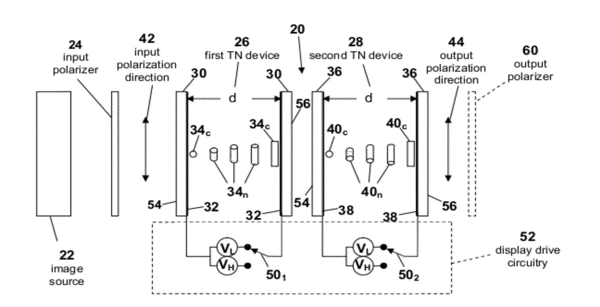
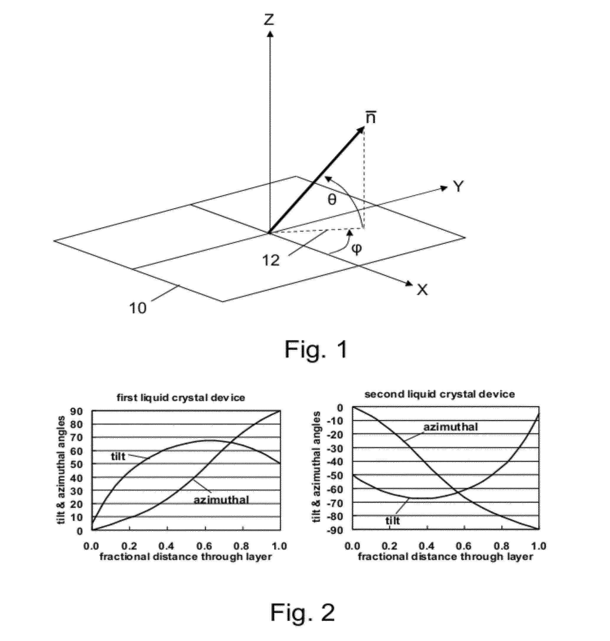
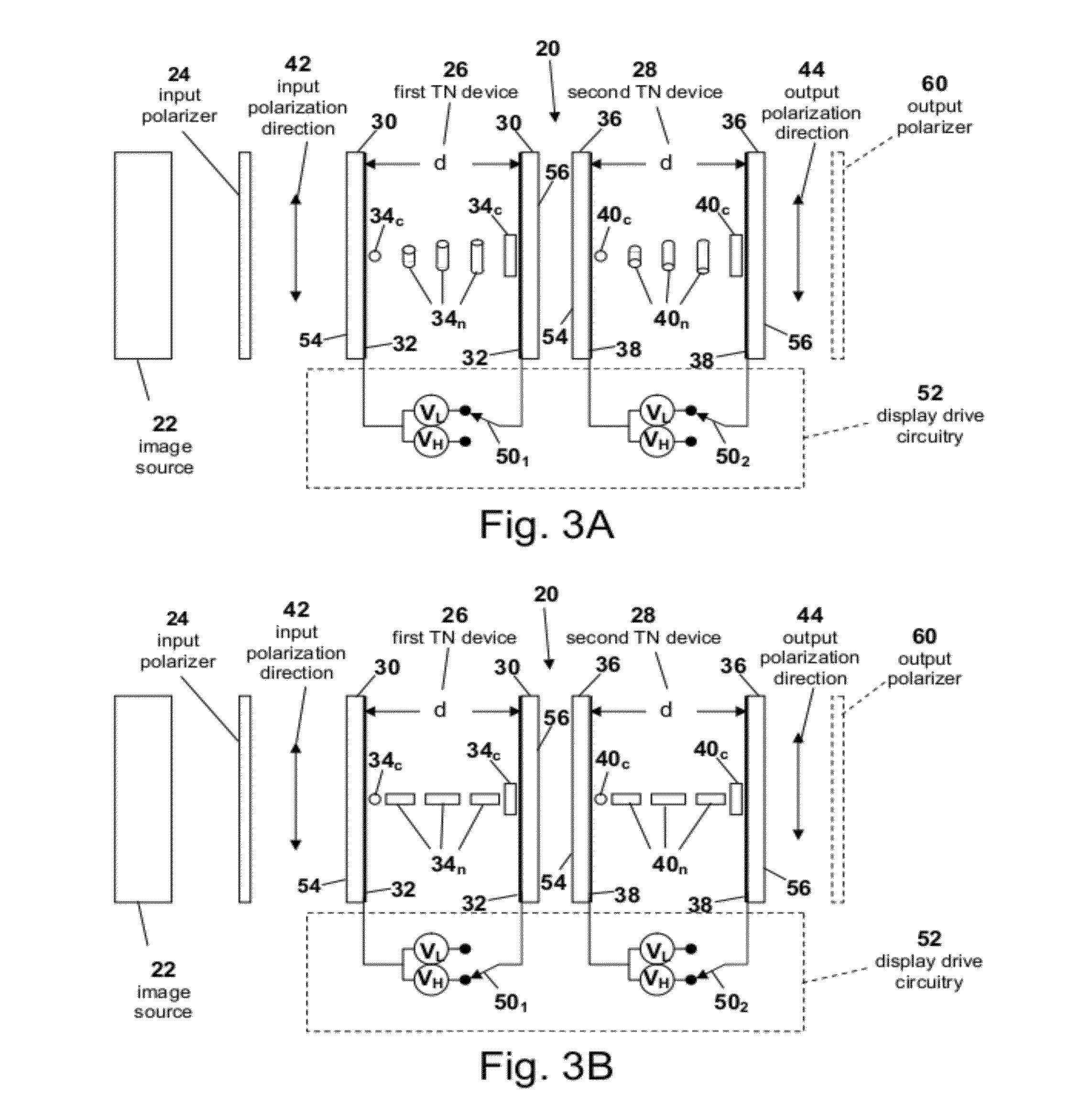
[0018]A useful property of two compensating liquid crystal devices is that, if the same voltage is applied to both of them, one liquid crystal device compensates a change that the other liquid crystal device makes to the input polarization state, regardless of the applied voltage level. Moreover, if the applied voltage is changed from one level to another and the liquid crystal material in the liquid crystal devices relaxes to the new voltage level, polarization state compensation will take place throughout the duration of the relaxation. This is referred to as dynamic compensation. Thus, if a voltage is applied to both liquid crystal devices and then removed, they will continue to compensate throughout the relaxation process with no change in the polarization state of the light passing through the combination. The slow, unpowered transition of the liquid crystal devices does not, therefore, manifest itself as a change in polarization state. The disclosed drive scheme takes advantage of this latter property, which enables fast-switching polarization modulator operation because the two liquid crystal devices are allowed to reset to the lower voltage polarization state by the slower, unpowered transition without any optical change.

Problems solved by technology

A problem with using a TN device as a polarization switch is that the transition from a high voltage optical state to a low voltage optical state is too slow for many applications because the restoring torque on the liquid crystal directors comes only from elastic forces propagating from the fixed boundary alignment established by the directors contacting the processed inner surfaces of the electrodes.
Even with low viscosity, high birefringence liquid crystal materials and the liquid crystal display device technology now available, the high voltage optical state to low voltage optical state transition is still on the order of 2 ms to 3 ms, which is too slow for use in modern time-multiplexed stereoscopic 3D applications, in which complete left or right eye images might be available for only 4 ms or less.
There are, however, several problems associated with the two frequency technology.
First, this scheme is incapable of switching uniformly over a large area because of formation of domains or patches in the liquid crystal device.
Second, the crossover frequency, i.e., the frequency at which the dielectric anisotropy of the liquid crystal changes sign, is very temperature dependent and as a consequence limits the temperature range in which the device can successfully operate.
Third, the high frequency drive signal feeding into the capacitive load of the liquid crystal device requires significant power, which precludes using this system in battery operated, portable devices such as active stereoscopic 3D glasses.
This pi-cell mode switches faster than does the TN mode because the internal liquid crystal material flow associated with switching of the pi-cell does not introduce a slowing “optical bounce.” Nevertheless, the high voltage optical state to low voltage optical state transition is still an unpowered transition, with a response time of about 1 ms using present materials and device technology.
However, there are many drawbacks of ferroelectric polarization modulators.
First, the liquid crystal device is required to have a very thin cell gap, on the order of 1 μm, which makes it difficult to manufacture ferroelectric liquid crystal devices with high yield.
Second, the alignment of the ferroelectric layers is very sensitive to shock and pressure variations, which sensitivity rules out many applications that entail manipulation, such as use in active stereoscopic 3D glasses worn by an observer.
Third, variations in temperature can also cause alignment disruptions, especially if the temperature is temporarily raised above the smectic transition temperature.
This scheme is unsuitable for time-multiplexed stereoscopic 3D applications, which operate with two time intervals (left and right image subframes) of substantially equal durations.
A disadvantage of this scheme is that both transitions incorporate the comparatively slow unpowered transition, which can introduce image crosstalk, loss of brightness, and other artifacts in modern time-multiplexed stereoscopic 3D applications.
Both liquid crystal devices are simultaneously driven with the same waveforms, resulting in a very fast optical response when both liquid crystal devices are switched from a low voltage optical state to a high voltage optical state because they are powered transitions, but the simultaneous transitions from high to low voltage optical states are unpowered transitions and are therefore comparatively slow, reducing switching performance for time multiplexing stereoscopic 3D applications.
This arrangement gives superior performance in welding applications, in which extremely high optical density over wide viewing angles is required, but would not be suitable for time multiplexing stereoscopic 3D applications because of the slow optical response of the unpowered transitions.

Method used


Image

  • High-speed liquid crystal polarization modulator
  • High-speed liquid crystal polarization modulator
  • High-speed liquid crystal polarization modulator

Examples


second embodiment

[0077]FIG. 7 shows for a second preferred embodiment the drive signal conditions for TN polarization modulator 20, in which analyzing or output polarizer 60 is combined with polarization modulator 20 to enable it to act as a light shutter in active glasses for stereoscopic 3D viewing in conjunction with image source 22 showing left eye and right eye image subframes. The left and right eyepiece lens assemblies in the active glasses have the same structures, each comprising first TN device 26 and second TN device 28, as shown in FIG. 3A, placed between input polarizer 24 and output polarizer 60. The light transmission polarization axes of input polarizer 24 and output polarizer 60 are set at a right angle to each other. The drive signal waveforms for first and second TN devices 26 and 28 of the right eyepiece lens are shown in FIG. 7, lines (a) and (b) and for the left eyepiece lens in FIG. 7, lines (c) and (d). The drive signal waveforms for the left eye are the same as those for the...

fourth embodiment

[0087]The fourth embodiment using two ECB devices 84 and 86 constructed with a nematic liquid crystal mixture having positive dielectric anisotropy has been realized experimentally. Each of the ECB devices was made using indium tin oxide (ITO) coated glass substrates, and liquid crystal director alignment was provided with rubbed polyimide such that, when the two substrates were assembled, the rub directions on the top and bottom substrates were anti-parallel to each other. The pretilt angle of the surface-contacting directors was about 4°, and a cell gap, d, of 2.5 μm was provided using spacers in the seal material. The ECB liquid crystal devices were filled with the nematic liquid crystal mixture MLC-7030 available from Merck KGaA, Darmstadt, Germany. The MLC-7030 mixture has a birefringence of 0.1102.

[0088]FIGS. 10A and 10B show the drive signal waveforms applied to first and second ECB devices 84 and 86. In this case, the subframe period was 5.0 ms, corresponding to a frequenc...


PUM

PropertyMeasurementUnit
response timeaaaaaaaaaa
voltagesaaaaaaaaaa
angleaaaaaaaaaa

Abstract

A polarization modulator for time-multiplexed stereoscopic 3D applications rapidly switches between two polarization states in alternate subframes. The polarization modulator uses two liquid crystal devices arranged in optical series and driven such that the second device compensates a change the first device makes to an input polarization state of incident light during alternate subframes. The compensating liquid crystal devices are characterized in that, if the same voltage is applied to both of them, the second device compensates the change that the first device makes to the input polarization state, regardless of the applied voltage level. If the applied voltage is changed from one level to another and the liquid crystal material in the liquid crystal devices relaxes to the new voltage level, polarization state compensation will take place throughout the duration of the relaxation so that the slow, unpowered transition does not manifest itself as a change in polarization state.

Description

RELATED APPLICATION[0001]This is a continuation-in-part of U.S. patent application Ser. No. 12 / 858,349, filed Aug. 17, 2010.COPYRIGHT NOTICE[0002]©2011 LC-TEC Displays AB. A portion of the disclosure of this patent document contains material that is subject to copyright protection. The copyright owner has no objection to the facsimile reproduction by anyone of the patent document or the patent disclosure, as it appears in the Patent and Trademark Office patent file or records, but otherwise reserves all copyright rights whatsoever. 37 CFR §1.71(d).TECHNICAL FIELD[0003]The present disclosure relates to a high-speed, liquid crystal polarization modulator for time-multiplexed stereoscopic three-dimensional (3D) applications. More particularly, the disclosure relates to a polarization state modulator implemented with first and second liquid crystal devices through which incident light in an input polarization state propagates and in which the second liquid crystal device compensates a c...

Claims


Application Information

Patent Timeline
Patent Type & Authority Applications(United States)
IPC IPC(8): G02F1/1347G02B30/25
CPCG02F1/13471H04N13/0438G02B27/26G02F2203/07G02F1/13363H04N13/341H04N13/398G02B30/25G02F1/133637G02F1/133638
Inventor OSTERMAN, JESPERSCHEFFER, TERRY J.
Owner LC TEC DISPLAY
Learn More