Optical display device having polarizing film
- Summary
- Abstract
- Description
- Claims
- Application Information
AI Technical Summary
Benefits of technology
Problems solved by technology
Method used
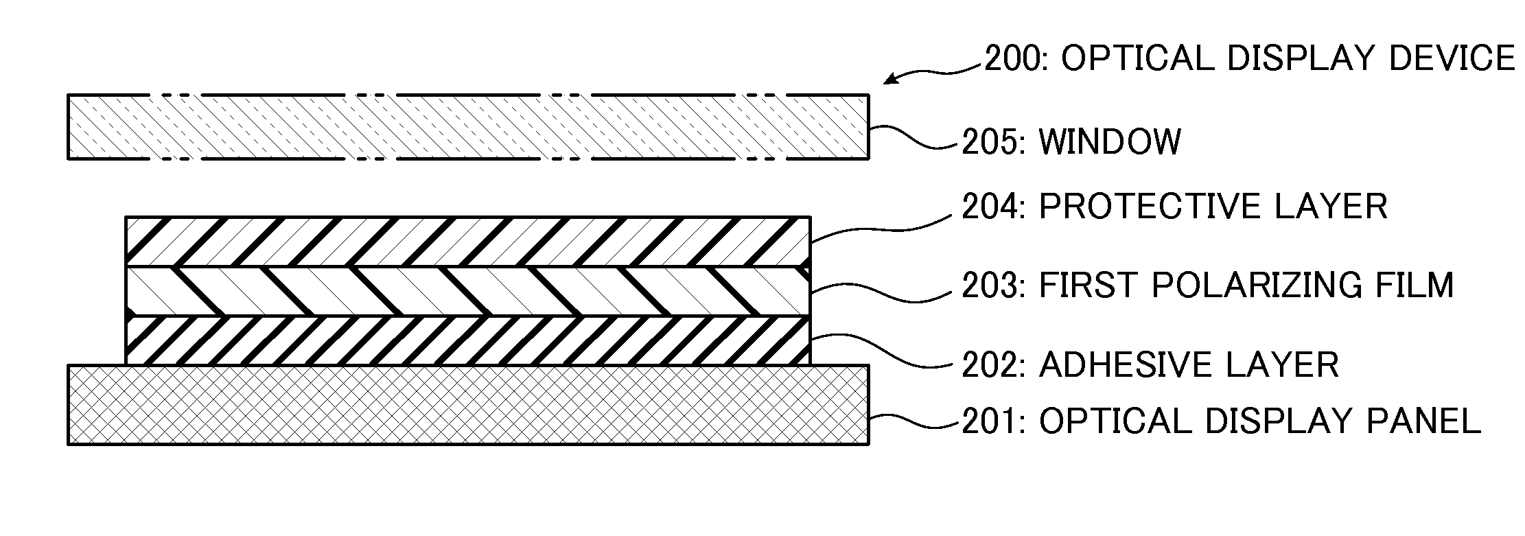
Image

Examples
example 1
[0132]A continuous web of substrate was prepared as a non-crystallizable ester type thermoplastic resin substrate comprising isophthalic acid-copolymerized polyethylene terephthalate copolymerized with 6 mol% of isophthalic acid (hereinafter referred to as “non-crystallizable PET”). The non-crystallizable PET has a glass transition temperature of 75° C. A laminate comprising the continuous web of non-crystallizable PET substrate and a polyvinyl alcohol (hereinafter referred to as “PVA”) layer was prepared in the following manner. By the way, PVA has a glass transition temperature of 80° C.
[0133]A non-crystallizable PET substrate having a thickness of 200 μm was prepared, and a PVA aqueous solution having a PVA concentration of 4 to 5 wt % was also prepared by dissolving a PVA powder having a polymerization degree of 1000 or more and a saponification degree of 99% or more in water. Then, the PVA aqueous solution was applied to the 200 μm-thick non-crystallizable PET substrate, and dr...
example 2
[0142]In the Example 2, as with the Example 1, a 7 μm-thick PVA layer was formed on a non-crystallizable PET substrate to form a laminate, and then the laminate including the 7 μm-thick PVA layer was subjected to preliminary in-air stretching and stretched at a stretching ratio of 1.8 to form a stretched laminate, whereafter the stretched laminate was immersed in a dyeing solution containing iodine and potassium iodide and having a temperature of 30° C. to form a dyed laminate including an iodine-absorbed PVA layer. Differently from the Example 1, a process in the Example 2 additionally comprises a cross-linking step. The cross-linking step is designed to immerse the dyed laminate in a cross-linking boric acid aqueous solution at a temperature of 40° C., for 60 seconds, so as to allow PVA molecules of the iodine-absorbed PVA layer to be subjected to cross-linking. The cross-linking boric acid aqueous solution in this step was set to contain 3 weight parts of boric acid with respect ...
example 3
[0146]In the Example 3, as with the Example 1, a 7 μm-thick PVA layer was formed on a non-crystallizable PET substrate to form a laminate, and then the laminate including the 7 μm-thick PVA layer was subjected to preliminary in-air stretching and stretched at a stretching ratio of 1.8 to form a stretched laminate. Differently from the Example 1, a process in the Example 3 additionally comprises an insolubilization step. The insolubilization step is designed to immerse the stretched laminate in a boric acid insolubilizing aqueous solution at a solution temperature of 30° C., for 30 seconds, so as to insolubilize a PVA layer included in the stretched laminate and having oriented PVA molecules. The boric acid insolubilizing aqueous solution in this step was set to contain 3 weight parts of boric acid with respect to 100 weight parts of water. A technical effect expected of the insolubilization step in the Example 3 is to prevent the PVA layer included in the stretched laminate from bei...
PUM
| Property | Measurement | Unit |
|---|---|---|
| Length | aaaaa | aaaaa |
| Thickness | aaaaa | aaaaa |
| Transparency | aaaaa | aaaaa |
Abstract
Description
Claims
Application Information
PatSnap Eureka turns technology decisions into work you can execute. Powered by our Innovation Knowledge Graph, it runs expert workflows across engineering, life sciences, materials and intellectual property. Get your review-ready output in minutes.


