Tube Picking Mechanisms with an Ultra-Low Temperature or Cryogenic Picking Compartment

a technology of which is applied in the field of tube picking mechanism, can solve the problems of not being able the environment within the ultra-low temperature or cryogenic freezer compartment is typically too cold to ensure reliable operation of conventional tube picking mechanism, and it is not normally desirable to remove an entire sbs tube rack. , to achieve the effect of reducing ice and frost formation, dispersing to the surrounding environment, and different dimensions

Active Publication Date: 2012-03-15
HAMILTON STORAGE TECH
View PDF1 Cites 70 Cited by
  • Summary
  • Abstract
  • Description
  • Claims
  • Application Information

AI Technical Summary

Benefits of technology

[0009]The tube picking mechanism also includes an upper compartment in which the temperature is warmer (e.g. preferably about −20° C. to −30° C.) than the temperature (e.g. −80° C.) of the lower compartment in the tube picking chamber. The bottom portion of the upper compartment is adjacent to the top portion of the lower compartment forming a warm-cold boundary therebetween. Tube picking is accomplished in the lower ultra-low temperature (e.g. −80° C.) or cryogenic compartment whereas active mechanical and electrical components are housed in the warmer, upper compartment. Structural components pass from the warmer, upper compartment into the ultra-low temperature or cryogenic lower compartment in order to enable movement of mechanical components necessary to pick tubes from storage racks. Thermal stratification helps to maintain the ultra-low or cryogenic temperature of the refrigerated, lower compartment without the need for sealing along the warm-cold boundary between the upper compartment and the lower compartment. It is desirable that components passing from the upper compartment into the ultra-low temperature or cryogenic lower compartment be made of insulating materials with low thermal conductivity.
[0010]In the preferred embodiment of the invention, the tube picking mechanism includes a picker plate located in the ultra-low temperature or cryogenic, lower compartment. The picker plate holds at least one tube storage rack and preferably has nesting locations for several storage racks. Each storage rack nest on the picker plate preferably has an opening that allows access from below the picker plate to the bottom side of the storage rack placed on the plate. Storage rack nests for destination racks, as contrasted to source racks, do not necessarily require access from below the picker plate. At least one door is provided along the upper surface of the lower compartment to allow robotic access for placing and retrieving storage tube racks into the refrigerated, ultra-low temperature or cryogenic lower compartment. The location of the door utilizes thermal stratification to reduce the heat gain when opening and closing the door.
[0013]It is preferred that the upper compartment be enclosed with a non-thermally insulated vapor barrier. It is desirable that the heat generated by the active electrical and mechanical components in the upper compartment dissipate to the surrounding environment. On the other hand, it is important to prevent moisture from entering into the tube picking mechanism in order to reduce ice and frost formation.
[0014]In one desirable embodiment, the picker plate is a rotary picker plate having several storage plate nesting locations spaced circumferentially around the plate. A rotary drive mechanism is provided in the warmer, upper compartment to rotate the picker plate so that the desired nesting location is located beneath the gripping fingers of the tube picking head. It is desirable for the rotary picker plate to also include a biasing corner reference mechanism, such as spring loaded biasing fingers, adjacent to each nest for the purpose of corner referencing the storage rack in a known fixed position within the nest. This is important because the nest dimensions need to be large enough to accommodate a number of different types of storage racks that may have somewhat different dimensions. It has been found that even SBS format storage racks have somewhat different dimensions especially when cooled to ultra-low or cryogenic temperatures. The biasing mechanism not only reduces movement of the racks during operation but also locates the rack in a precise corner referenced position which facilitates reliable tube picking. It is further desirable that the system include a motorized release mechanism to mechanically release the corner reference mechanism in order to enable the placement and removal of storage tube racks in the respective nesting locations. Preferably, this is accomplished with a motorized rotary drive located in the warmer, upper compartment, which turns a downwardly extending rod having a rotating finger that mechanically moves the corner reference mechanism against the direction of bias.
[0015]Another embodiment of the invention uses a Cartesian picker plate instead of a rotary picker plate. In this embodiment of the invention, a linear drive mechanism is provided in the upper compartment to move the tube picking head horizontally in one Cartesian direction. Another linear drive mechanism is provided in the upper compartment to move the picker plate mechanism horizontally in a perpendicular Cartesian direction. These linear drive mechanisms allow the tube picking head to access all of the tubes in all the storage racks on the picker plate. The embodiment of the invention having a rotary picker plate, on the other hand, also has linear drive mechanisms to move the tube picking head into alignment with tubes in the storage rack located beneath the gripping jaws of the picker head but the horizontal range of motion of the picker head in the rotary embodiment is substantially less than in the Cartesian embodiment. The smaller range of motion enables the rotary embodiment to have less open area in the partition plate between the upper and lower compartments.

Problems solved by technology

It is not normally desirable to remove an entire SBS tube rack from the system through the I / O module when only one or a few tubes from a given storage rack are desired to be retrieved.
The removal procedure may allow for the ingress of moisture into the system, and also renders the other samples held in the same tube rack susceptible to warming and thawing, at least partially, even if the tube rack is removed from the system temporarily.
While tube picking mechanisms are generally known in the art, the environment within an ultra-low temperature or cryogenic freezer compartment is typically too cold to ensure reliable operation of conventional tube picking mechanisms.
One issue is that the electrical, pneumatic and hydraulic components are unreliable at such ultra-low temperatures.
Also thermal expansion and contraction of robotic components and storage racks can cause significant mechanical difficulties if not properly addressed.
Another issue is that the formation of frost and ice is exacerbated due to the low moisture saturation point in ultra-low temperature or cryogenic environments.
At such low temperatures, the air can hold very little moisture so any moisture introduced into the freezer environment tends to form frost on the cold surfaces within the environment.
Frost and ice accumulation can interfere with the removal of tubes from racks and with the insertion of tubes into the racks.
In addition, the moving parts of a tube picker in the freezer environment can become contaminated with ice and cause mechanisms to jam.
To date, tube picking mechanisms have been commercially used in low temperature (e.g. −20° C.) environments, but as mentioned it is difficult or impractical to operate a tube picking mechanism in ultra-low temperature or cryogenic environments.
However, as mentioned previously, exposure of samples even to a −20° C. environment may cause undesirable warming.

Method used


Image

  • Tube Picking Mechanisms with an Ultra-Low Temperature or Cryogenic Picking Compartment
  • Tube Picking Mechanisms with an Ultra-Low Temperature or Cryogenic Picking Compartment
  • Tube Picking Mechanisms with an Ultra-Low Temperature or Cryogenic Picking Compartment

Examples


Embodiment Construction

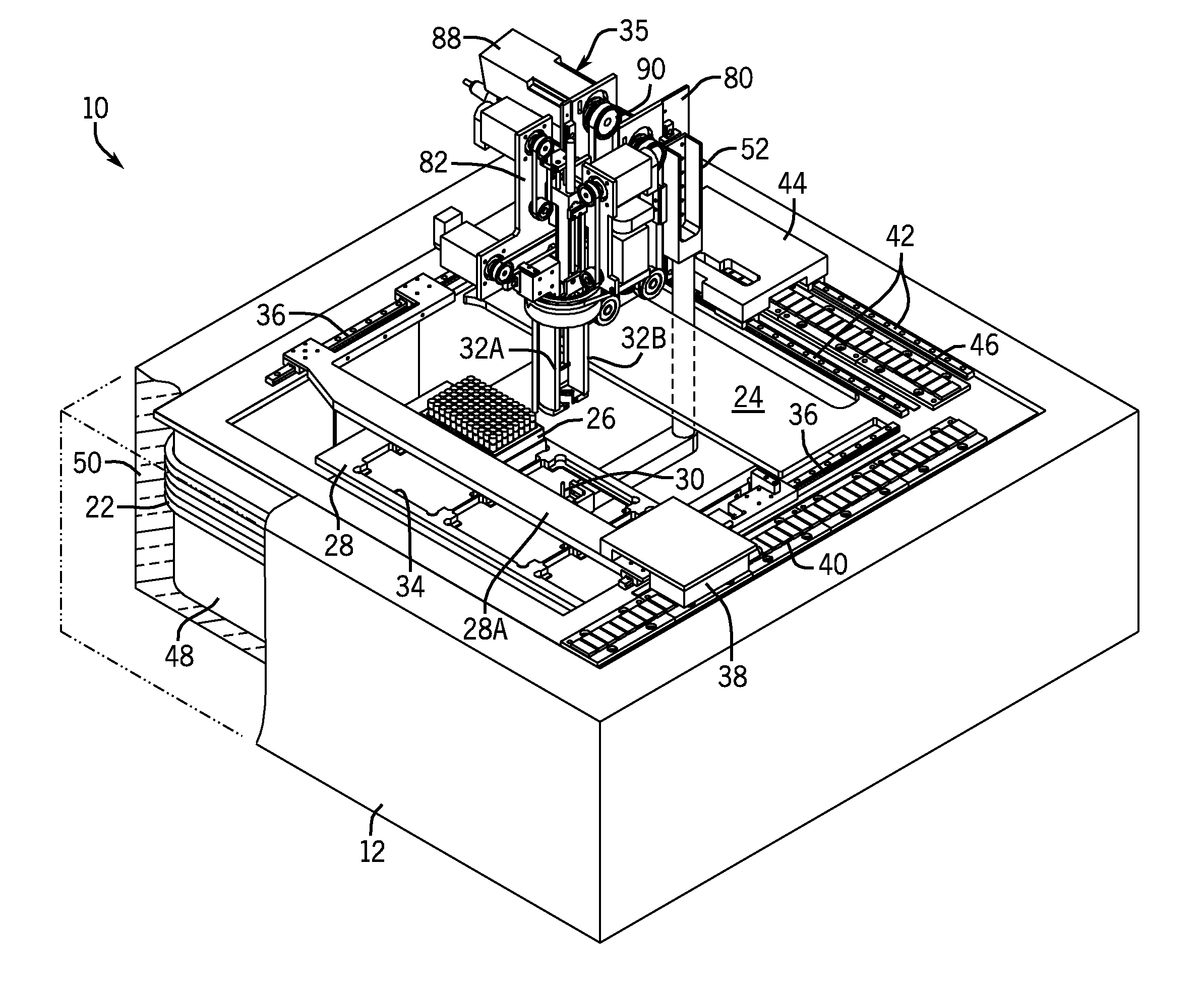
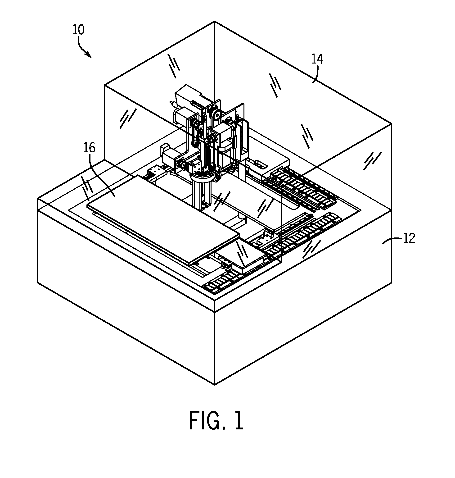
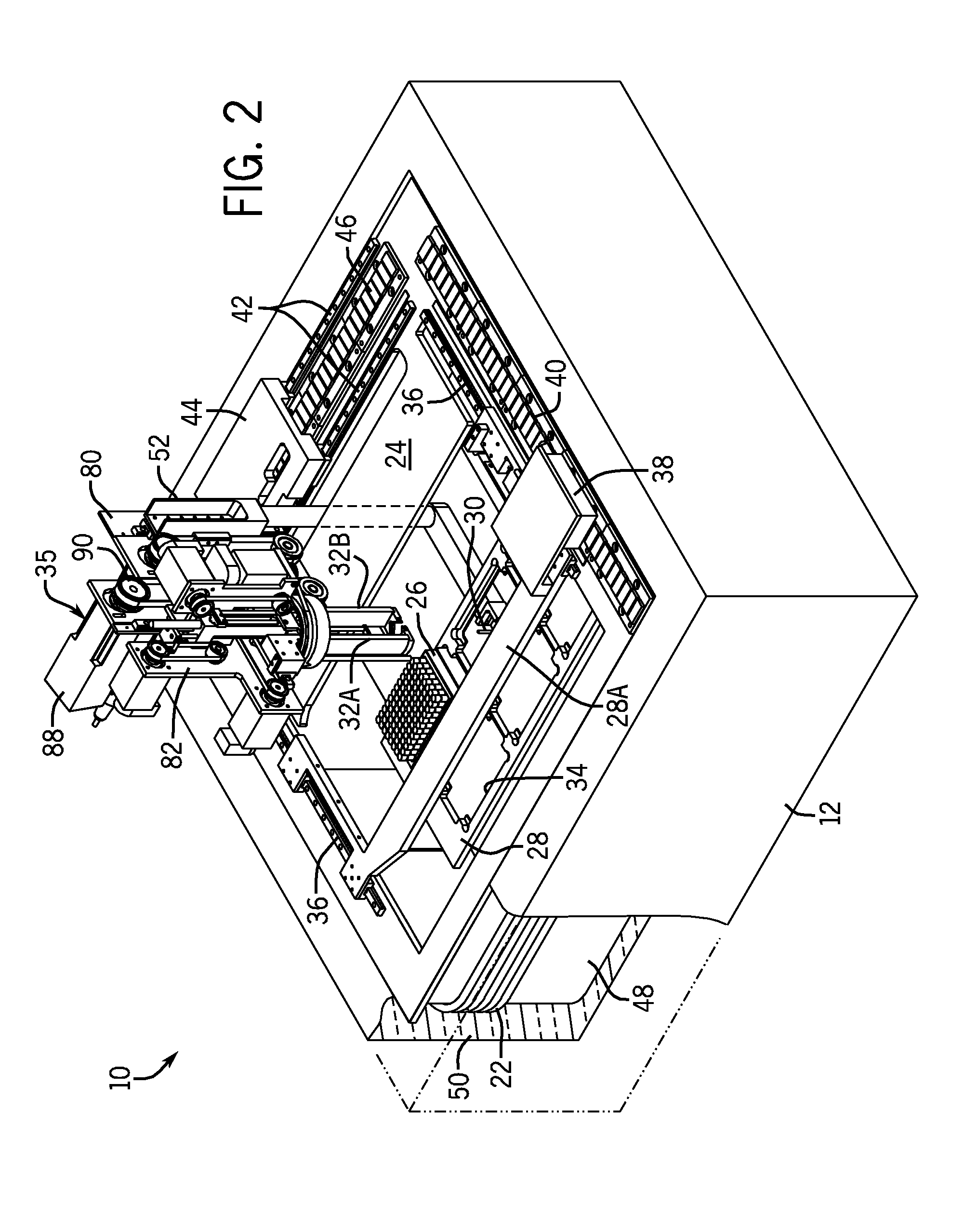
[0039]FIG. 1 is a perspective view of a tube picking mechanism 10 that is constructed in accordance with a first exemplary embodiment of the invention. The tube picking mechanism shown in FIG. 1 includes a chamber 12 that is refrigerated to an ultra-low temperature (e.g., below −50° C. and desirably about −80° C. in most non-cryogenic applications) when the tube picking mechanism 10 is in operation. The tube picking mechanism is designed to be used to pick tubes from racks stored in an ultra-low temperature freezer system. In a typical ultra-low temperature application (e.g., about −80° C.) it is desirable that the temperature of the refrigerated chamber 12 be cooled to the temperature or near the temperature at which samples are stored in the system freezers; however, the invention is not limited to this condition. For example, as mentioned above in the event that the tube picking mechanism is used in connection with a cryogenic freezer system, it will normally be desirable to cool...


PUM


Abstract

A tube picking mechanism is designed for use in an automated, ultra-low temperature (e.g. −80° C. or −135° C.) or cryogenic (e.g., about −140° C. to −196° C.) storage and retrieval system that stores biological or chemical samples. The samples are contained in storage tubes held in SBS footprint storage racks that are normally stored within an ultra-low temperature or cryogenic freezer compartment. The tube picking mechanism includes a tube picking chamber that is maintained at about −80° C., about −135° C. or at cryogenic temperatures in cryogenic applications. Active electrical and mechanical components are maintained in a compartment above and separate from the refrigerated, ultra-low temperature or cryogenic compartment. Thermal stratification inhibits heat transfer into the lower, ultra-low temperature or cryogenic compartment in which tube picking occurs from the upper compartment in which active electrical and mechanical components are located, and also inhibits heat transfer into the lower, ultra-low temperature or cryogenic compartment via an access door for tube storage racks.

Description

FIELD OF THE INVENTION[0001]The invention is directed to tube picking mechanisms having a tube picking compartment maintained at an ultra-low temperature, e.g. from about −50° C. to about −135° C. or at a cryogenic temperature (e.g., about −140° C. to −196° C.). The tube picking mechanisms are particularly well suited for use in an automated, ultra-low temperature or cryogenic storage and retrieval system used to store and retrieve biological and chemical samples.BACKGROUND OF THE INVENTION[0002]Storage of biological and chemical samples is becoming widespread in biotechnological and medical industries. Many of these samples must be stored at or below freezing temperatures. Generally speaking, a regular freezer operates from about −5° C. to −20° C., an ultra-low temperature freezer operates from about −50° C. to about −90° C. (preferably at about −80° C.) and a cryogenic freezer operates from about −140° C. to −196° C. (boiling point of liquid nitrogen). For some applications, it is...

Claims


Application Information

Patent Timeline
Patent Type & Authority Applications(United States)
IPC IPC(8): F25D25/00F25B9/04B66F11/00F25B21/02
CPCF25D11/04F25D13/04G01N35/0099F25D25/04G01N1/42F25D13/06A01N1/0242A01N1/0257
Inventor WARHURST, JULIANZANDI, BRUCECARBONE, ALEXANDERHUNT, FRANKCLOUTIER, ROBERTO'TOOLE, JAMESALEXANDER, ELIZABETH
Owner HAMILTON STORAGE TECH
Why Eureka
Try Eureka