Common Mode Noise Reduction Apparatus and Method

a technology of noise reduction apparatus and power converter, which is applied in the direction of electric variable regulation, process and machine control, instruments, etc., can solve the problems of common mode noise, high and fast voltage swing across the primary side, and isolating dc/dc converters may generate common mode noise, etc., to reduce common mode noise

Active Publication Date: 2012-03-15
HUAWEI DIGITAL POWER TECH CO LTD
View PDF0 Cites 21 Cited by
  • Summary
  • Abstract
  • Description
  • Claims
  • Application Information

AI Technical Summary

Benefits of technology

[0006]These and other problems are generally solved or circumvented, and technical advantages are generally achieved, by preferred embodiments of the present invention which provide an apparatus and method for reducing common mode noise in an isolated power converter.

Problems solved by technology

In a telecommunication network power system, isolated dc / dc converters may generate common mode noise.
Such a high switching frequency may generate a high and fast voltage swing across the primary side.
The high frequency voltage swing and the parasitic capacitors lead to common mode noise in an isolated dc / dc converter because the parasitic capacitors of the transformer provide a low impedance conductive path for common mode current derived from the high frequency voltage swing.
However, an effective common mode choke may be of a large inductance value, which may require a big and expensive coil.
Such a big and expensive coil may increase the size of the isolated dc / dc converter, introduce extra cost and degrade the efficiency of the isolated dc / dc converter as well.

Method used


Image

  • Common Mode Noise Reduction Apparatus and Method
  • Common Mode Noise Reduction Apparatus and Method
  • Common Mode Noise Reduction Apparatus and Method

Examples


Embodiment Construction

[0028]The making and using of the presently preferred embodiments are discussed in detail below. It should be appreciated, however, that the present invention provides many applicable inventive concepts that can be embodied in a wide variety of specific contexts. The specific embodiments discussed are merely illustrative of specific ways to make and use the invention, and do not limit the scope of the invention.

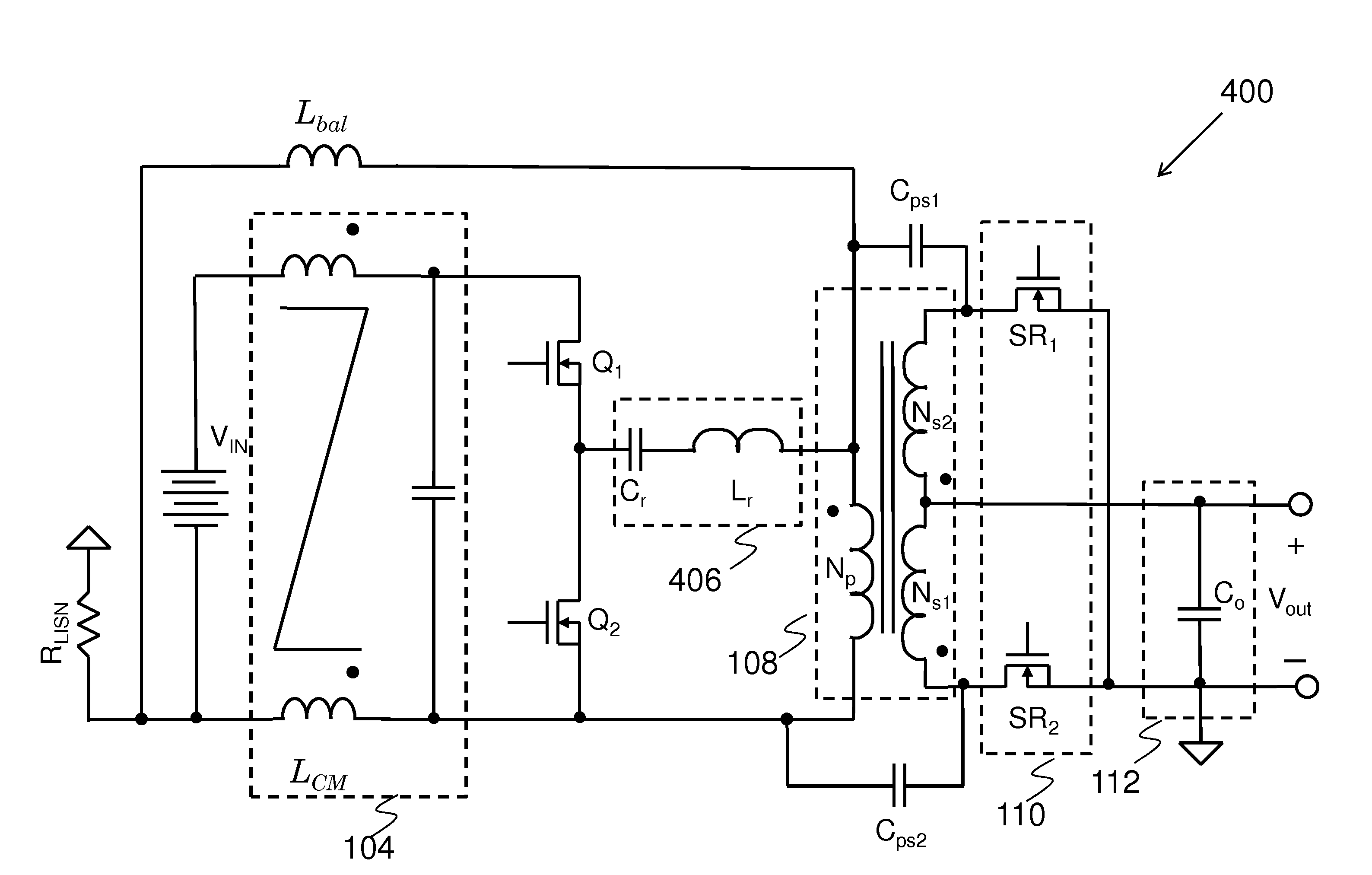
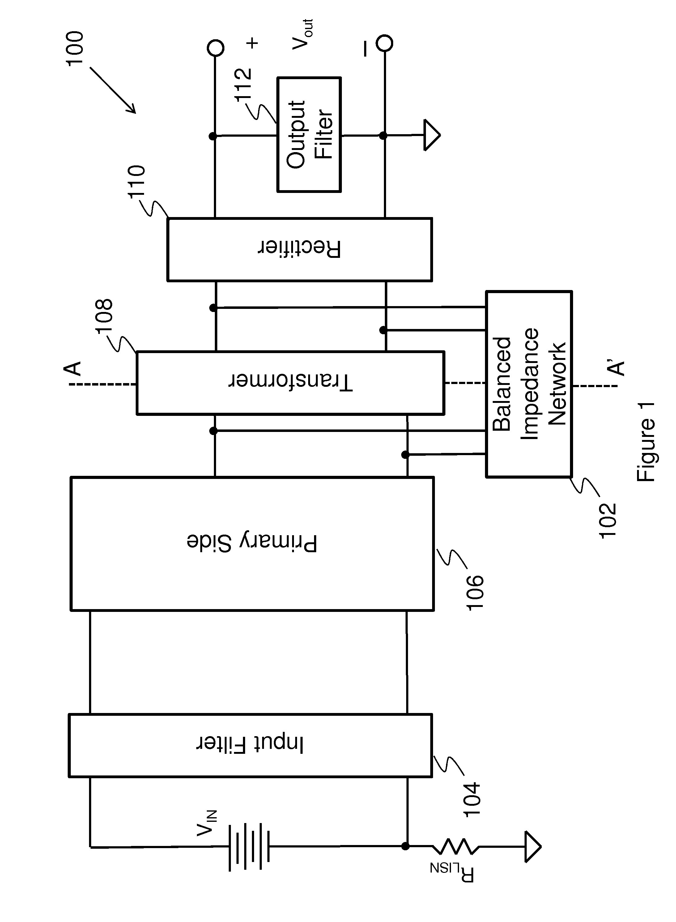
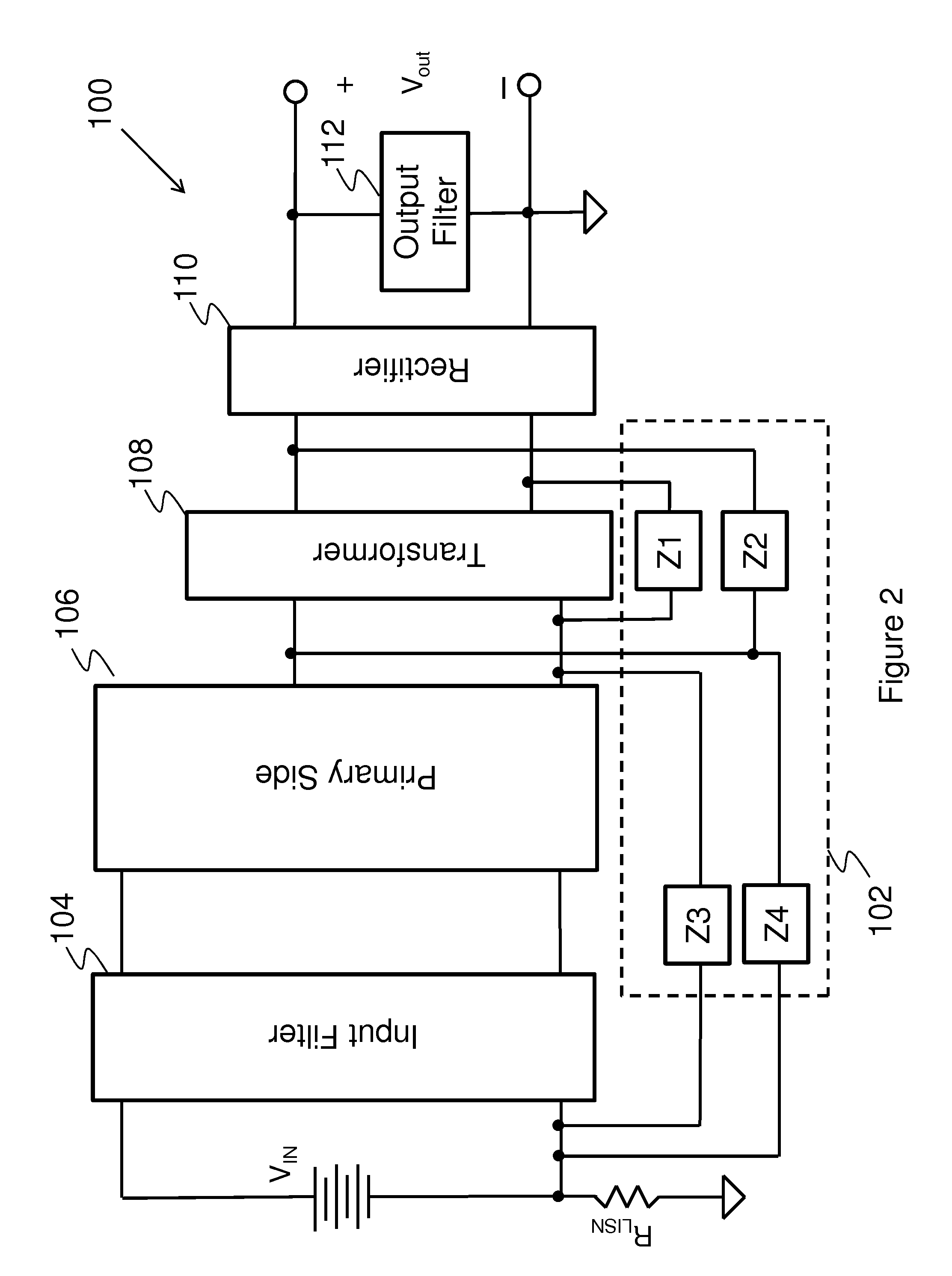
[0029]The present invention will be described with respect to preferred embodiments in a specific context, namely a common mode noise reduction apparatus of a series parallel resonant converter. Throughout the description, the series parallel converter is alternatively referred to as an LLC resonant converter since the series parallel converter is commonly known as an LLC resonant converter. The invention may also be applied, however, to a variety of isolated power converters including half bridge converters, full bridge converters, flyback converters, forward converters, pus...


PUM

PropertyMeasurementUnit
voltageaaaaaaaaaa
switching frequencyaaaaaaaaaa
inductanceaaaaaaaaaa

Abstract

An embodiment common mode noise reduction apparatus comprises a common mode choke, a balance inductor, a first capacitor and a second capacitor. The common mode choke is placed between an input dc source and a primary side network of an isolated power converter. The balance inductor is coupled between an upper terminal of a primary winding of the isolated power converter and a negative terminal of the input dc source. The first capacitor is coupled between the upper terminal of a primary side of a transformer and an upper terminal of a secondary side of the transformer of the isolated power converter. The second capacitor is coupled between a lower terminal of the primary side of the transformer and a lower terminal of the secondary side of the transformer of the isolated power converter.

Description

[0001]This application claims the benefit of U.S. Provisional Application No. 61 / 382,229, filed on Sep. 13, 2010, entitled “Novel EMI Reduction Techniques for DC-DC Converters,” which application is hereby incorporated herein by reference.TECHNICAL FIELD[0002]The present invention relates to a common mode noise reduction apparatus and method for power converters, and more particularly, to a common mode noise reduction apparatus and method for a series parallel resonant converter.BACKGROUND[0003]A telecommunication network power system usually includes an ac-dc stage converting the power from the ac utility line to a 48V dc distribution bus and a dc / dc stage converting the 48V dc distribution bus to a plurality of voltage levels for all types of telecommunication loads. A conventional ac-dc stage may comprise a variety of EMI filters, a bridge rectifier formed by four diodes, a power factor correction circuit and an isolated dc / dc power converter. The dc / dc stage may comprise a plura...

Claims


Application Information

Patent Timeline
Patent Type & Authority Applications(United States)
IPC IPC(8): H02M3/335G01R31/28
CPCH02M2001/123Y10T29/49004H02M3/28H02M1/123
Inventor FU, DIANBOMAO, HENGCHUNCAI, BING
Owner HUAWEI DIGITAL POWER TECH CO LTD
Why Eureka
Try Eureka