Head model for brain-imaging device and technique for producing same

a brain-imaging device and head model technology, applied in the field of head models, can solve the problems of easy air trapped between slices, inability to perform hypothetical verification, so as to facilitate the operation of discharging air remaining from the injection of test solution, easy to confirm, and easy to remov

Inactive Publication Date: 2012-03-22
NIHON MEDI PHYSICS CO LTD +1
View PDF12 Cites 16 Cited by
  • Summary
  • Abstract
  • Description
  • Claims
  • Application Information

AI Technical Summary

Benefits of technology

[0014]Furthermore, by selecting transparent materials for the structure and the liquid being filled, it becomes possible to observe the inside of the phantom, it is easy to confirm whether air has entered the phantom, and, furthermore, if air has entered, it is easy to remove that air. This is a highly excellent property that has not been available in head phantoms that have been proposed in the past.
[0015]Moreover, in the head model described above, the part corresponding to the skull and the part corresponding to at least one specific region of the brain are each formed as a single hollow structure with no cuts, no discontinuous parts other than an opening for liquid injection. In other words, unlike conventional head models, the brain region is not segmented by a sliced structure, and is not discontinuous. Due to these characteristics, the problem seen in the prior art of air remaining between the slices does not occur in pri...

Problems solved by technology

However, because the head model of FIG. 1 has a form in which sheet-like members resembling slices are contained in a columnar container, it is not possible to perform verification that takes into consideration the actual shape of the head or the effects of bones.
However, because it is clearly impossible to change retroactively the material or thickness of the part corresponding to the skull, it is not possible to perform verification for a hypothetical case in which the skull has no effect, or to perform measurements while changing the absorption coefficient, etc. of the skull.
Moreover, a serious problem with conventional head models is that, because the head models are formed as multiple slices as shown in FIG. 1 and FIG. 2, it is easy for air to become trapped between slices, and it is not easy to remove air that has become trapped.
Because air has different γ-ray absorption characteristics from the other tissue, it becomes a significant cause of e...

Method used


Image

  • Head model for brain-imaging device and technique for producing same
  • Head model for brain-imaging device and technique for producing same
  • Head model for brain-imaging device and technique for producing same

Examples


Embodiment Construction

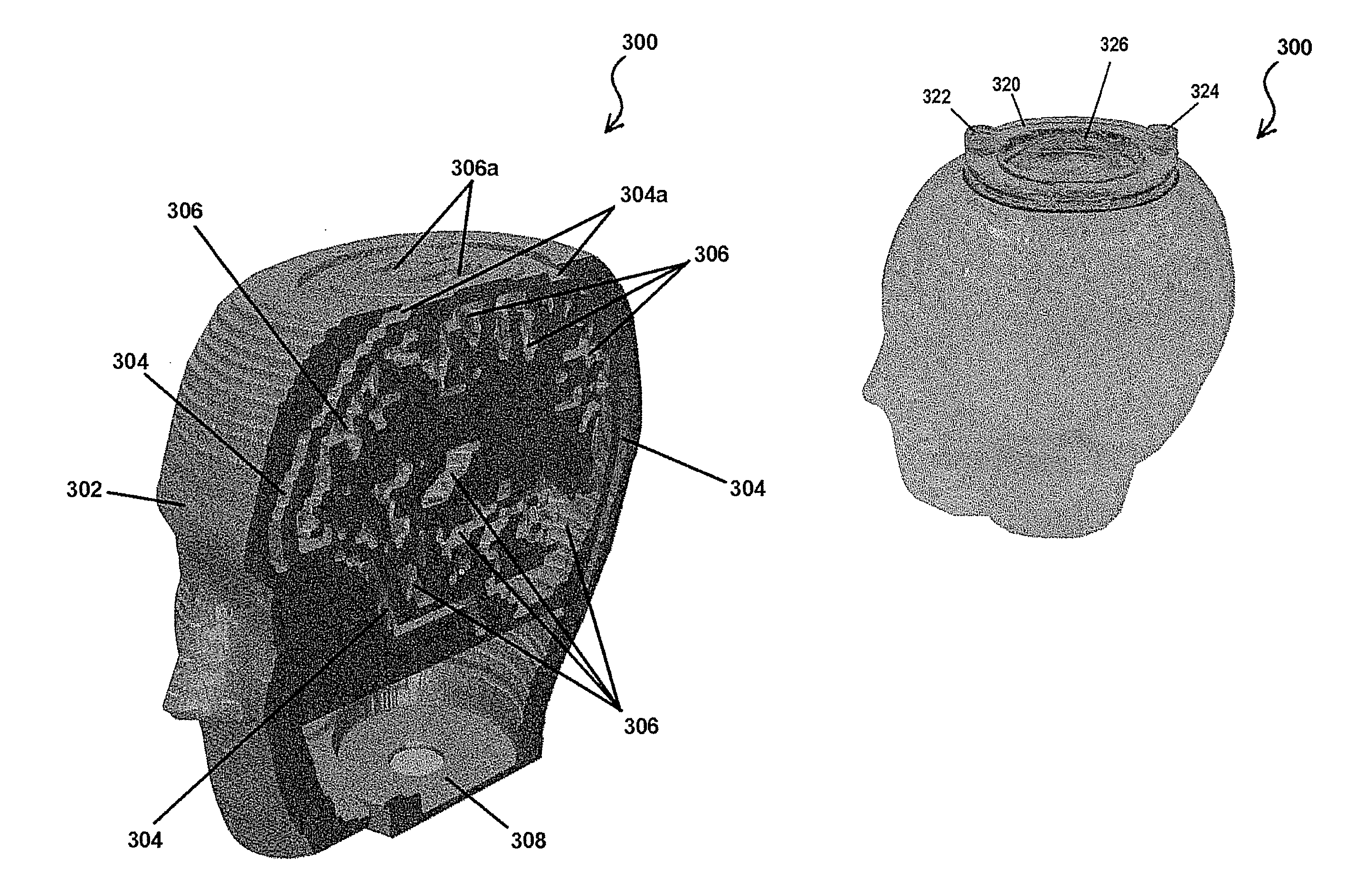
[0038]FIGS. 3A to 3C and FIGS. 4A and 4B are images for explaining one embodiment of the head model according to the present invention. FIG. 3A and FIG. 3B are perspective views of a head model 300 according to the present embodiment, viewed from the front and the rear, respectively, and FIG. 3C shows the same head model 300 in a transparent perspective view. FIG. 4A shows the head model 300 in a cross-sectional view (sagittal view). The head model 300 has a structure in which a cavity 304 resembling the shape of the skull and a cavity 306 resembling a specific region of the brain are formed inside a solid structure 302.

[0039]The structure 302 may be composed of, for example, acryl or ABS resin. The external appearance of the structure 302 is arbitrary, but as shown in FIG. 3A and FIG. 3C, it is preferably a shape resembling the outer surface shape of a human head, such as the shapes near the eyes and nose. Moreover, to make the measurements closer to measurements of an actual human...


PUM

PropertyMeasurementUnit
Fractionaaaaaaaaaa
Shapeaaaaaaaaaa
Transparencyaaaaaaaaaa

Abstract

A head model according to one example of an embodiment is a head model that may be provided for use in the calibration for a brain-imaging device, where a part corresponding to the skull and a part corresponding to at least one specific region of the brain are each formed by a continuous cavity with no cuts other than an opening for liquid injection.

Description

TECHNOLOGICAL FIELD[0001]The present invention is related to a head model that may be used for applications such as verification or adjustment for brain-imaging technologies such as PET or SPECT, and to technology for manufacturing the same.BACKGROUND ART[0002]Brain imaging is widely performed using various techniques in order to diagnose brain diseases or to study brain functions. PET (Positron Emission Tomography) or SPECT (Single Photon Emission Computed Tomography) is one example of such brain-imaging techniques. In these methods, photons (gamma rays) that are directly or indirectly generated from a radioactive drug injected into the body are detected by multiple gamma-ray detectors arranged around the head, and a brain image is formed by imaging the distribution of those photons using a computer. PET and SPECT are suitable techniques for imaging information on physiological function, such as neurotransmitter receptor distribution, glucose consumption, local blood flow, vascular...

Claims


Application Information

Patent Timeline
IPC IPC(8): G09B23/28G06F19/00F16K51/00
CPCB29C67/0066G09B23/30G09B23/286B29C64/135Y10T137/9464B29C67/00B65D51/24G09B23/28
Inventor IIDA, HIDEHIRONAKAZAWA, MAYUMIIMBAYASHI, ETSUKOISHIDA, KENJI
Owner NIHON MEDI PHYSICS CO LTD
Why Eureka
Try Eureka