

Formulations for use in sulfur scale control in industrial water systems
a technology for industrial water systems and forms, applied in water/sludge/sewage treatment, specific water treatment objectives, chemistry apparatuses and processes, etc., can solve problems such as loss of efficiency in system transport through the system, corrosion of pipes, and blockage of liquid flow
- Summary
- Abstract
- Description
- Claims
- Application Information
AI Technical Summary
Benefits of technology
Problems solved by technology
Method used
Image

Examples
example 1
[0084]An estimate of 400,000 gallons of water in a cooling tower was treated with 20 gallons of 15% by wt of a formulation of a compound of Formula (I) (7.5 ppm active ingredient). The formulation loosened and removed the sulfur deposits from the nozzles. Sulfur was observed residing on the underlying fill (see FIGS. 7A and 7B). Other evidence of improved performance by use of the present formulation are:
[0085]1. Thermographic Analysis of Return Water in Cooling Tower:
[0086]The temperature of the cold water return flow measured horizontally across the flow as shown in FIG. 10 was compared for a system that was treated with the present formulation and an untreated system. The untreated system showed higher temperatures (30-44° C.) and the treated system showed lower temperatures (28-36° C.), which result demonstrates improved performance of the cooling system.
[0087]2. Turbidity:
[0088]The turbidity of the water in the cooling tower basin showed an increase from 4 to 60 FAU over a thre...
example 2
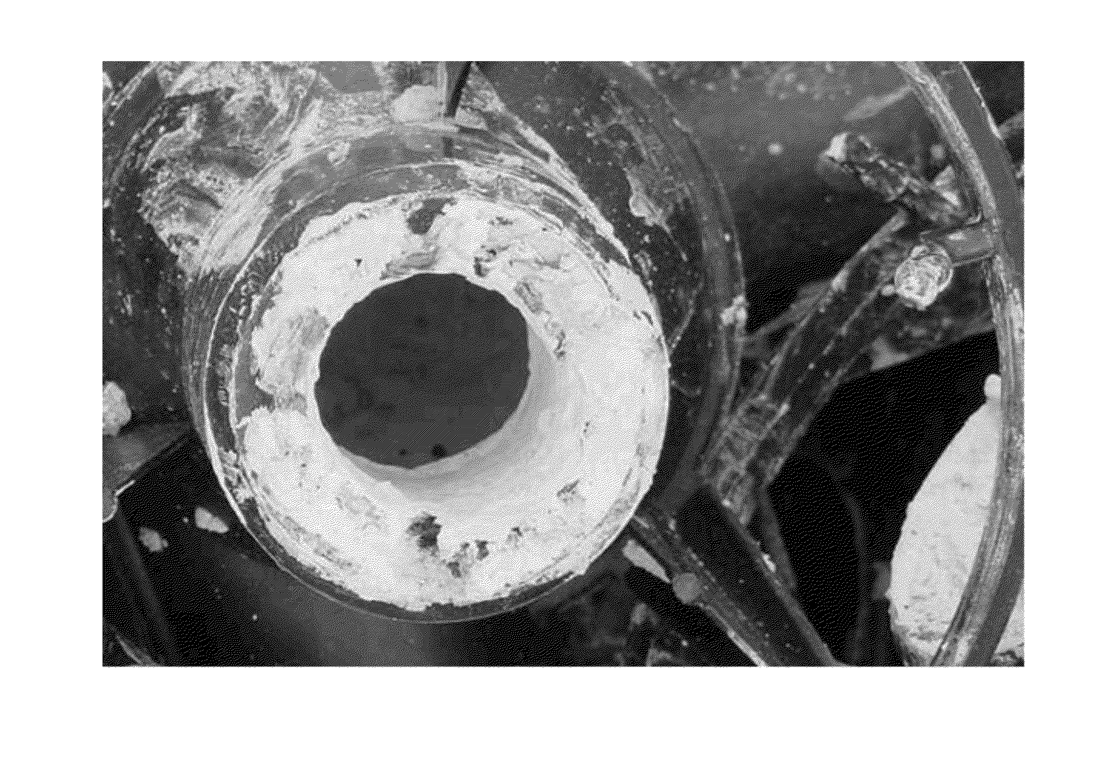
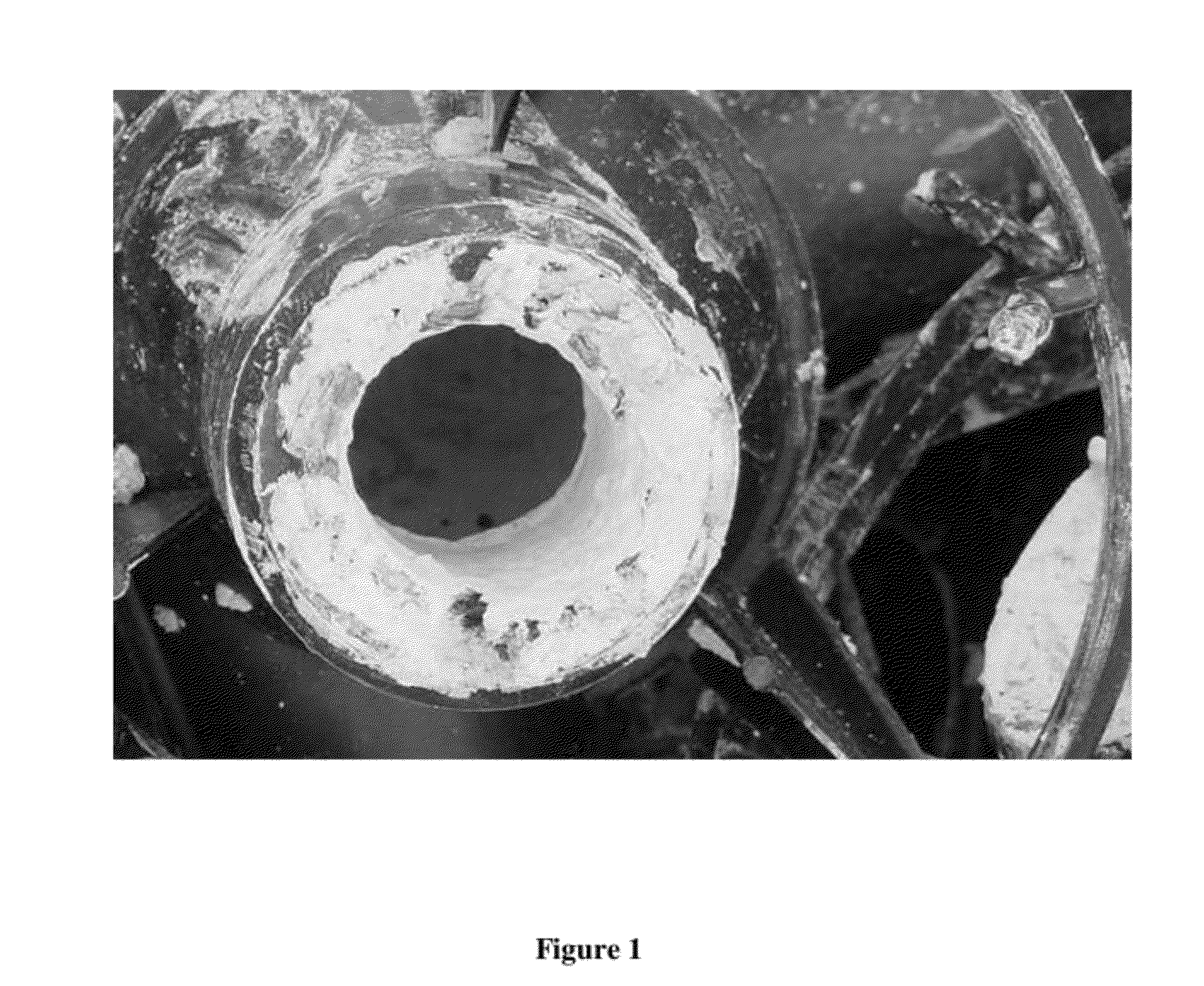
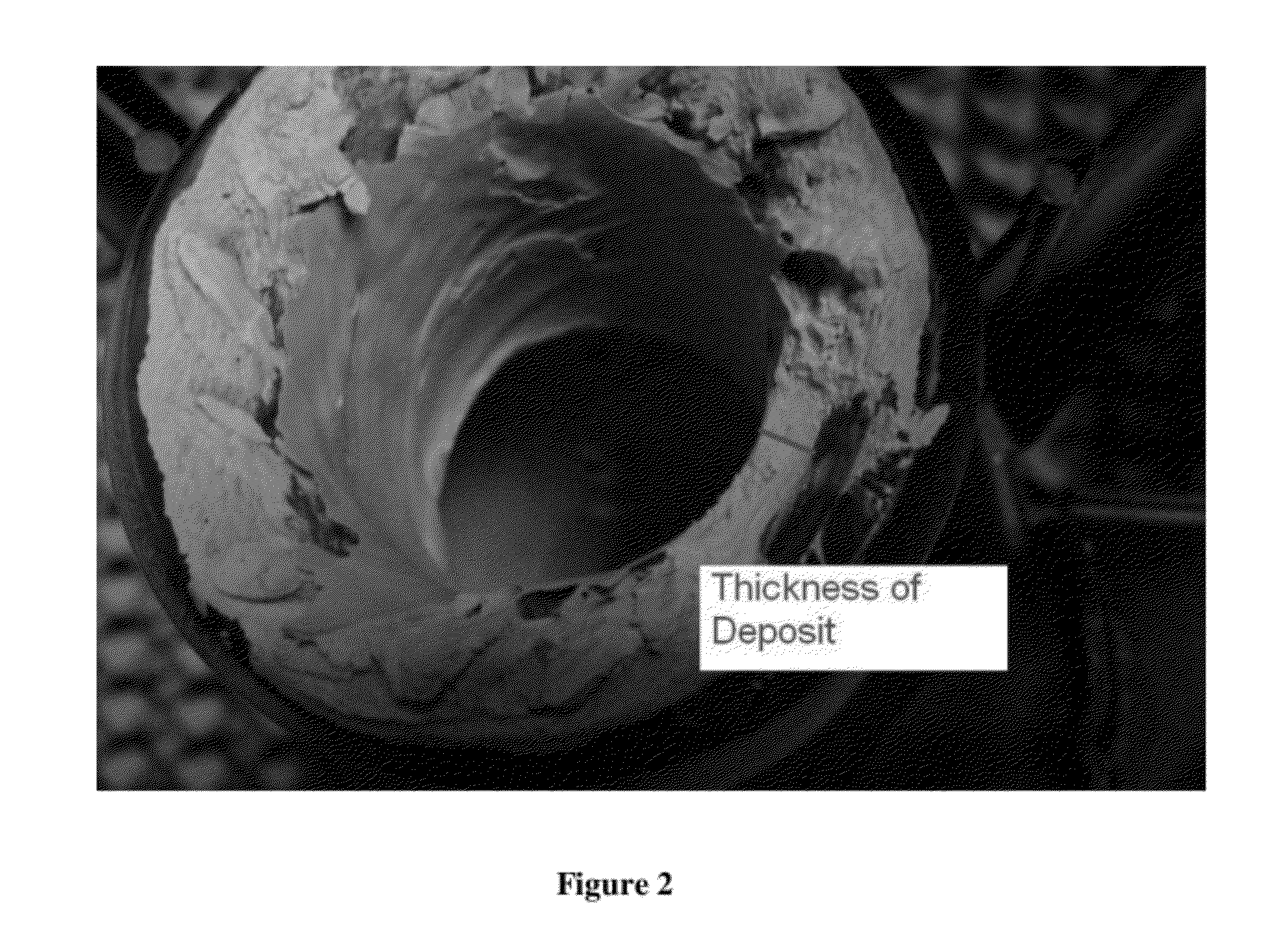
[0096]When geothermal towers are experiencing water distribution problems (see FIG. 10) often the nozzles and fill leads have Sulfur deposits. When the Sulfur deposits on the wetted surfaces of the nozzle, it will build to a significant depth at the nozzle orifice. This deposit changes the way the water emerges from the orifice and interacts with the impingement plate and results in a gradual narrowing of the spray pattern resulting in poor water distribution at the top of the fill. The water flow is concentrated directly underneath each nozzle, flooding these areas and leaving most of the rest of the fill nearly dry (see FIGS. 4 and 11). Also the water leaving the high flow areas is very hot whereas the water coming from the low flow areas is much cooler.
example 3
[0097]Fill fouling must be caught early or it becomes irreversible. If deposits grow so large that the circulating water cannot reach them (channeling) then treatment chemicals cannot reach them either so chemical cleanings become problematic. Cross corrugated fill is almost impossible to clean mechanically due to its design. Attempts usually lead to damage of the fill and impaction of the deposit material.
[0098]Loss of heat transfer efficiency is a negative consequence of fouling, but if unchecked fouling can cause even more problems. As Sulfur deposits grow, the plastic fill blocks can no longer support them and the fill crushes under its own weight. Mechanically damaged fill must be replaced. The weight of the fill can exceed the tolerance of the structure such that the fill supports collapse and dump the fill into the basin (see FIG. 3). This is very expensive, time consuming and loss of electrical output to the system for such repair.
PUM
| Property | Measurement | Unit |
|---|---|---|
| pressure | aaaaa | aaaaa |
| physical structure | aaaaa | aaaaa |
| loss of electrical output | aaaaa | aaaaa |
Abstract
Description
Claims
Application Information