Fuel vapor recovery system
a fuel vapor recovery and recovery system technology, applied in the direction of machine/engine, combustion air/fuel air treatment, separation process, etc., can solve the problems of difficult to efficiently separate the fuel vapor from air, the pressure in the permeation chamber is not controlled, etc., to improve the separation efficiency of the fuel vapor in the separator, the effect of reducing the concentration of the fuel vapor
- Summary
- Abstract
- Description
- Claims
- Application Information
AI Technical Summary
Benefits of technology
Problems solved by technology
Method used
Image
Examples
first embodiment
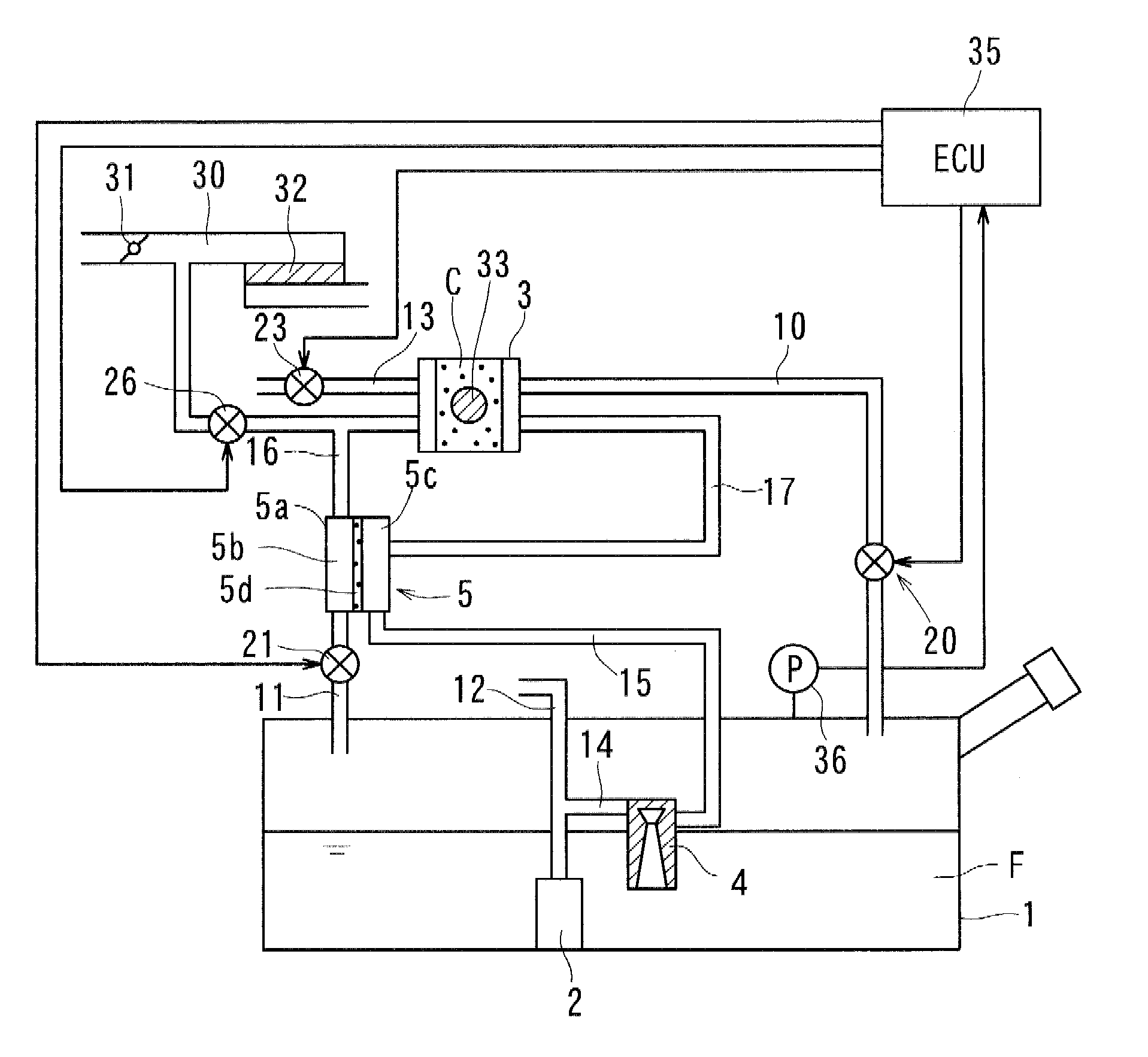
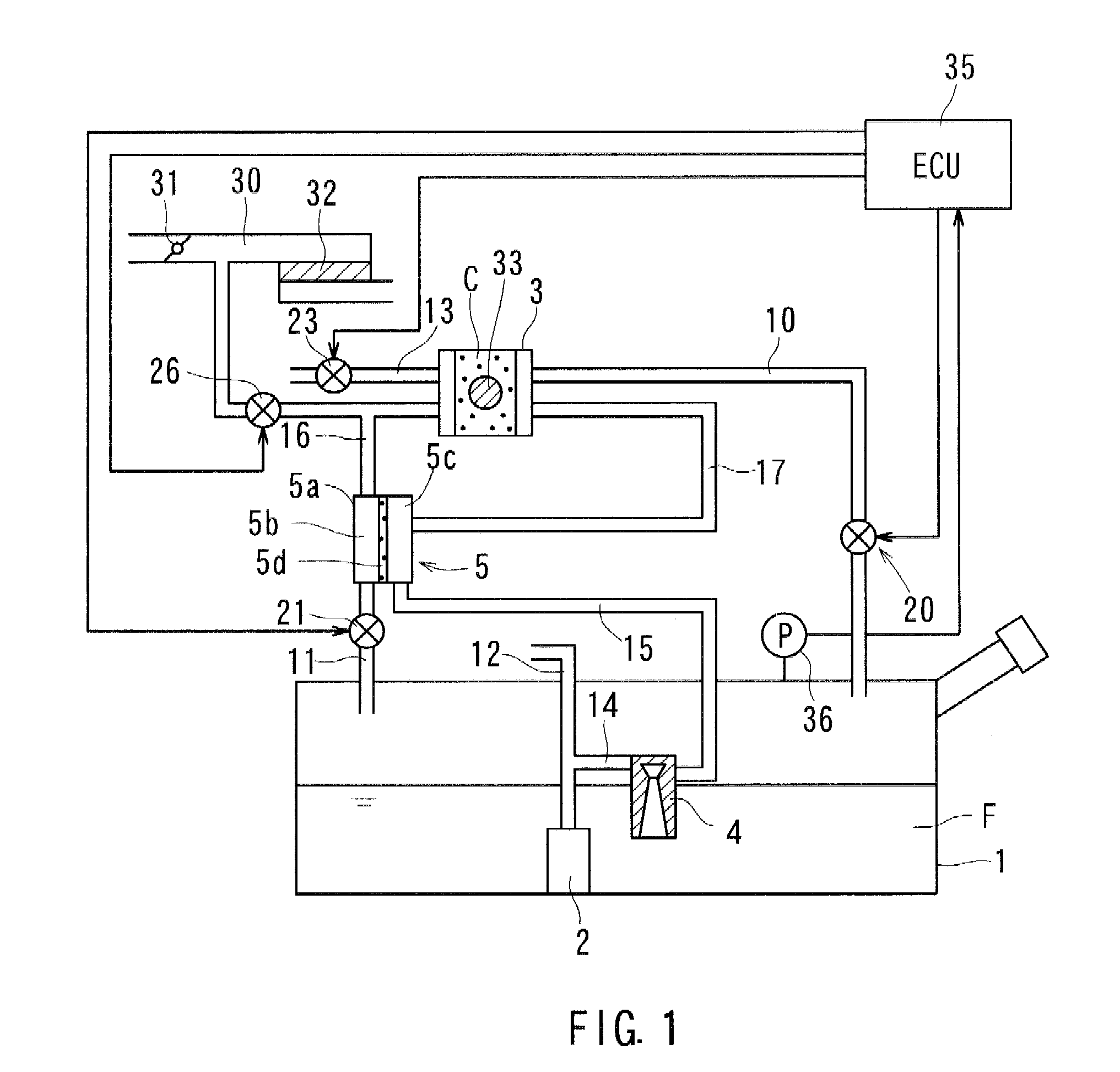
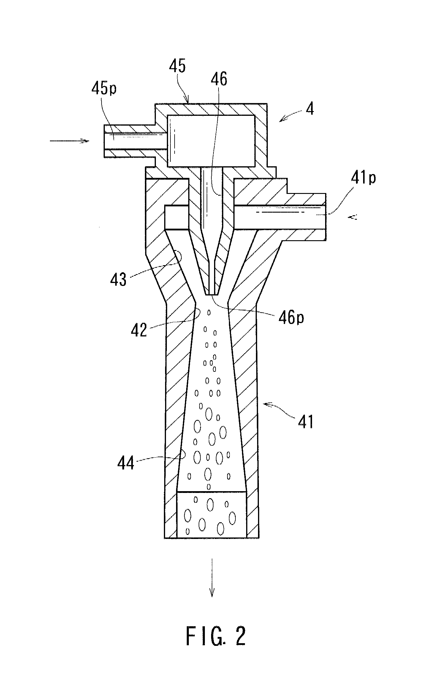
[0018]As shown in FIG. 1, a fuel vapor recovery system in a first embodiment has a fuel tank 1 reserving liquid fuel F therein, a fuel pump 2 pumping the liquid fuel F from the fuel tank 1 to an internal combustion engine (not shown), an adsorbent canister 3 capable of adsorbing and desorbing fuel vapor vaporized in the fuel tank 1, an aspirator 4 applying negative pressure to the adsorbent canister 3 in order to remove the fuel vapor from the adsorbent canister 3, a separation module 5 separating fuel vapor containing gas into air and the fuel vapor, a first introducing pipe 10 for introducing the fuel vapor from the fuel tank 1 into the adsorbent canister 3, and a second introducing pipe 11 for introducing the fuel vapor from the fuel tank 1 into the separation module 5. In this embodiment, the aspirator 4 and the separation module 5 correspond to a negative pressure supplier and a separator in this disclosure, respectively.
[0019]The fuel tank 1 is sealed. The fuel tank 1 has a pr...
second embodiment
[0042]As shown in FIG. 6, it is able to use a vacuum pump 55 as the negative pressure supplier instead of the aspirator 4. In this case, recovery process for the fuel vapor is substantially same as that in the first and
[0043]Although the separation module is separated into two units in the second embodiment, the separation module may be separated into at least three units. In such case, the separation module has a plurality of the connection pipes. The purge port 5p is preferably positioned at one of the connection pipes to meet both conditions that the purge port 5p is located at or downstream of the area where the concentration of the fuel vapor in the purge gas G4 is substantially equal to that in the permeation chamber and that the purge port 5p is located as upstream as possible with respect to the flow direction of the permeated gas G3 in the permeation chambers. Alternately, the purge port 5p may be formed on one of the units instead of the connection pipe.
PUM
| Property | Measurement | Unit |
|---|---|---|
| temperature | aaaaa | aaaaa |
| temperature | aaaaa | aaaaa |
| pressure | aaaaa | aaaaa |
Abstract
Description
Claims
Application Information
 - R&D Engineer
- R&D Manager
- IP Professional
- Industry Leading Data Capabilities
- Powerful AI technology
- Patent DNA Extraction
Browse by: Latest US Patents, China's latest patents, Technical Efficacy Thesaurus, Application Domain, Technology Topic, Popular Technical Reports.
© 2024 PatSnap. All rights reserved.Legal|Privacy policy|Modern Slavery Act Transparency Statement|Sitemap|About US| Contact US: help@patsnap.com


