Circuit for concurrent read operation and method therefor

a concurrent read and circuit technology, applied in the direction of information storage, static storage, digital storage, etc., can solve the problems of reducing the resistance of the a-si structure, reducing the endurance of the resistive device, and delay in read out, so as to simplify the circuit design, reduce the overall current and power consumption, and speed up the read operation

Active Publication Date: 2012-04-12
CROSSBAR INC
View PDF4 Cites 41 Cited by
  • Summary
  • Abstract
  • Description
  • Claims
  • Application Information

AI Technical Summary

Benefits of technology

[0016]Advantages of the present invention include one or more of the following: (1) reduce the overall current and power consumption by not having to pre-charge all the memory cells in an array; (2) eliminate or reduce the “pre-charge” phase of a read for a faster read operation; (3) simplify the circuit design since fewer biases would be required; (4) the bit lines used for reading would pre-charge to a closer absolute value since they are all adjacent to each other; (5) read disturb effect is reduced since all the memory cells in an array do not need to be pre-charged; and (6) redundancy scheme can be simplified since an array is divided into a plurality of memory units.

Problems solved by technology

In the case of a-Si structures, electric field-induced diffusion of metal ions into the silicon leads to the formation of conductive filaments that reduce the resistance of the a-Si structure.
However, the endurance of the resistive device can be shortened if excessive bias voltage is applied during the repeated write and erase cycles in part due to Joule heating and movements of an unnecessarily large number of metal ions in the a-Si structure.
This pre-charge requirement results in read out delays, increased read disturb, increased power consumption, and / or other disadvantages.

Method used


Image

  • Circuit for concurrent read operation and method therefor
  • Circuit for concurrent read operation and method therefor
  • Circuit for concurrent read operation and method therefor

Examples


Embodiment Construction

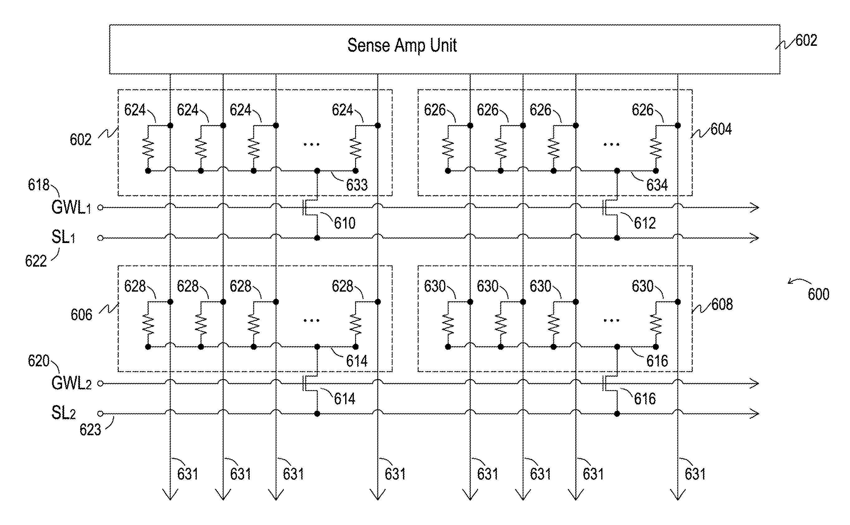
[0029]The present invention relates to a non-volatile memory device and a circuit for performing a concurrent read operation.

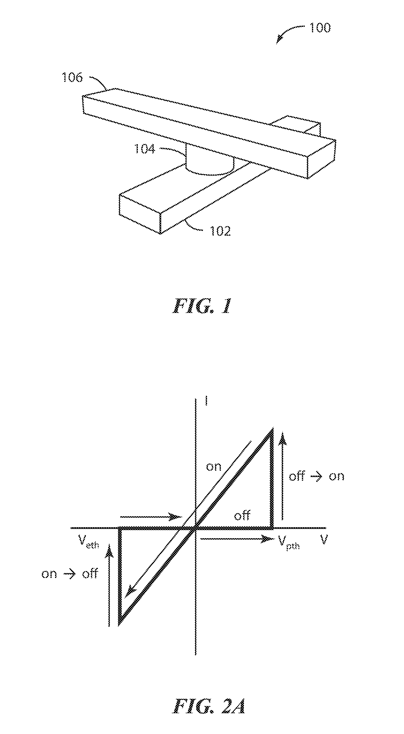
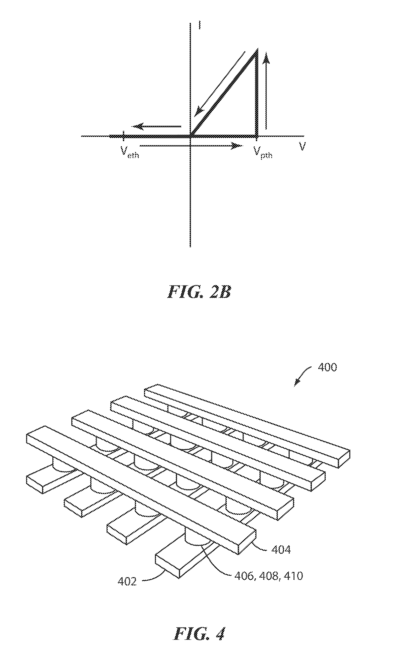
[0030]FIG. 1 illustrates a memory cell 100 in a non-volatile memory device, e.g., a semiconductor memory chip. The memory cell includes a bottom electrode 102, a switching medium 104, and a top electrode 106 according an embodiment of the present invention. The switching medium 104 exhibits a resistance that can be selectively set to various values, and reset, using appropriate control circuitry. The cell 100 is a two-terminal resistive memory device, e.g., resistive random-access memory (RRAM), in the present embodiment.

[0031]The resistive memory cell is a two-terminal memory cell having a switching medium provided between top and bottom electrodes. The resistance of the switching medium can be controlled by applying an electrical signal to the electrodes. The electrical signal may be current-based or voltage-based. As used herein, the term “RRAM” or “resisti...


PUM


Abstract

A non-volatile memory device includes a plurality of memory units provided in an array, each memory unit having a plurality of resistive memory cells and a local word line. Each resistive memory units has a first end and a second end, the second ends of the resistive memory cells of each memory unit being coupled to the local word line of the corresponding memory unit. A plurality of bit lines is provided, each bit line being coupled to the first end of one of the resistive memory cells. A plurality of select transistors is provided, each select transistor being assigned to one of the memory units and having a drain terminal coupled to the local word line of the assigned memory unit. First and second global word lines are provided, each global word line being coupled to a control terminal of at least one select transistor. First and second source lines are provided, each source line being coupled to a source terminal of at least one select transistor. The memory device is configured to concurrently read out all of the resistive memory cells in one of the memory units selected for a read operation.

Description

CROSS-REFERENCES TO RELATED APPLICATIONS[0001]NOT APPLICABLEBACKGROUND OF THE INVENTION[0002]The present invention relates to a resistive memory array architecture including resistive memory cells, in particular to a circuit and method for concurrently reading a plurality of memory cells in a resistive memory device.[0003]Resistive random-access memories (RRAMs) are a type of resistive memory and have generated significant interest recently as a potential candidate for ultra-high density non-volatile information storage. A typical RRAM device has an insulator layer provided between a pair of electrodes and exhibits electrical pulse induced hysteretic resistance switching effects.[0004]The resistance switching has been explained by the formation of conductive filaments inside the insulator due to Joule heating and electrochemical processes in binary oxides (e.g. NiO and TiO2) or redox processes for ionic conductors including oxides, chalcogenides and polymers. The resistance switchin...

Claims


Application Information

Patent Timeline
Patent Type & Authority Applications(United States)
IPC IPC(8): G11C7/06G11C11/21G11C5/06
CPCG11C7/18G11C13/0007G11C13/0028G11C2207/005G11C13/0061G11C2213/78G11C13/004G11C13/0002G11C13/0004G11C2213/15G11C7/06G11C13/00
Inventor KUO, HARRYNAZARIAN, HAGOP
Owner CROSSBAR INC
Why Eureka
Try Eureka