Battery charge/discharge control apparatus

Inactive Publication Date: 2012-04-26
HONDA MOTOR CO LTD
View PDF2 Cites 19 Cited by
  • Summary
  • Abstract
  • Description
  • Claims
  • Application Information

AI Technical Summary

Benefits of technology

[0018]According to the present invention, it is possible to provide a battery charge/discharge control apparatus that can simplify a control logic of whether an output of a battery is restricted in accordance with temperature history distribution of the

Problems solved by technology

Further, since output characteristics of such a battery largely depends upon its usage state (such as a travel distance, a driving method of a driver, frequency of use of acces

Method used


Image

  • Battery charge/discharge control apparatus
  • Battery charge/discharge control apparatus
  • Battery charge/discharge control apparatus

Examples


Example

First Embodiment

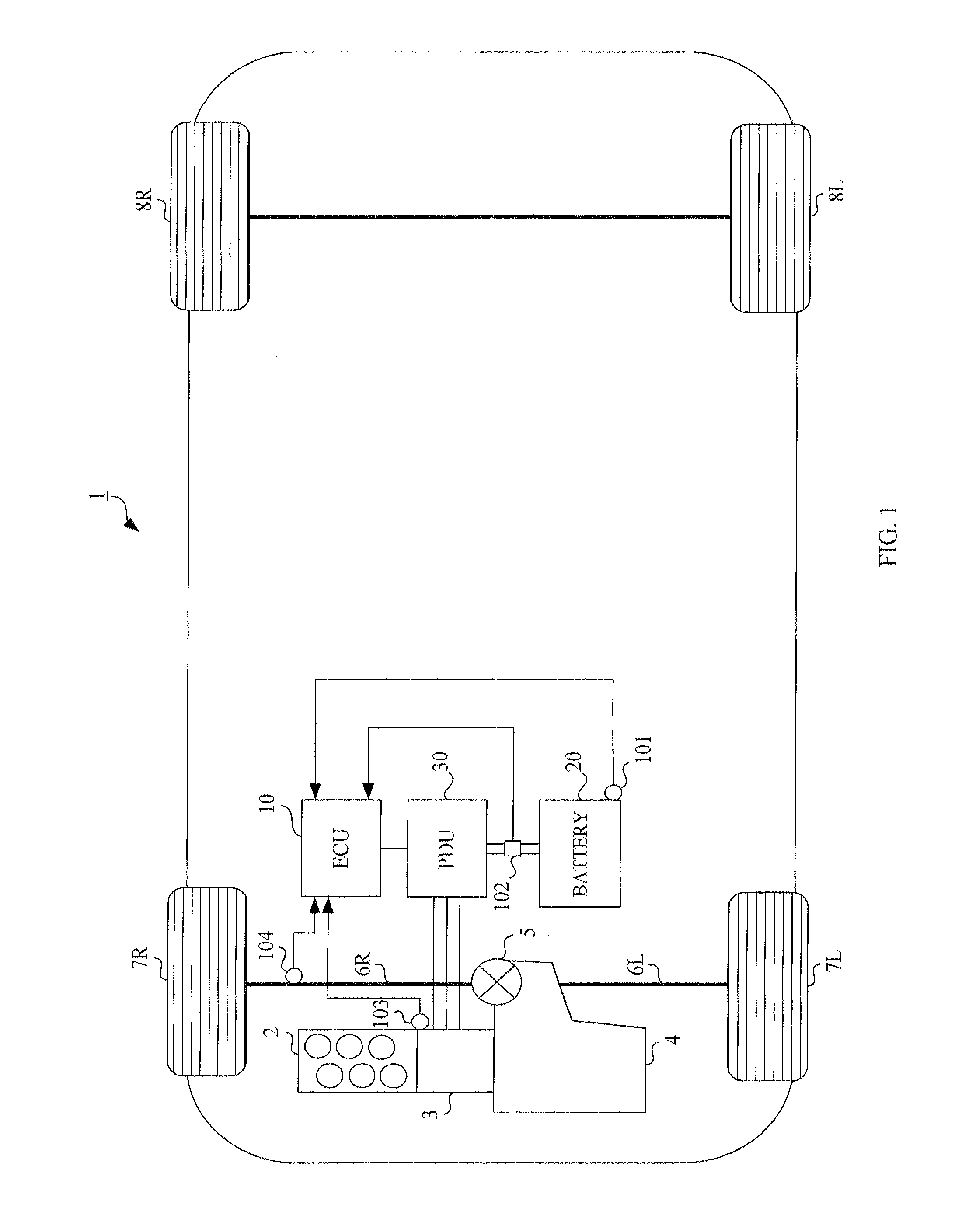
[0032]A configuration of a vehicle according to a first embodiment will first be described. FIG. 1 is a block diagram schematically showing a power transmission system and a control system of a vehicle. As shown in FIG. 1, a vehicle 1 according to the present embodiment is a so-called hybrid vehicle, and includes: an engine 2; an electric motor (motor) 3 disposed on an output shaft of this engine 2 and directly connected to the engine 2; a transmission (transmission) 4 connected to the output shaft of the engine 2 and the electric motor 3; a differential mechanism 5 connected to an output shaft of the transmission 4; right and left front wheels 7R, 7L, which are drive wheels, connected to this differential mechanism 5 via right and left axle shafts 6R, 6L; and right and left rear wheels 8R, 8L that are driven wheels.

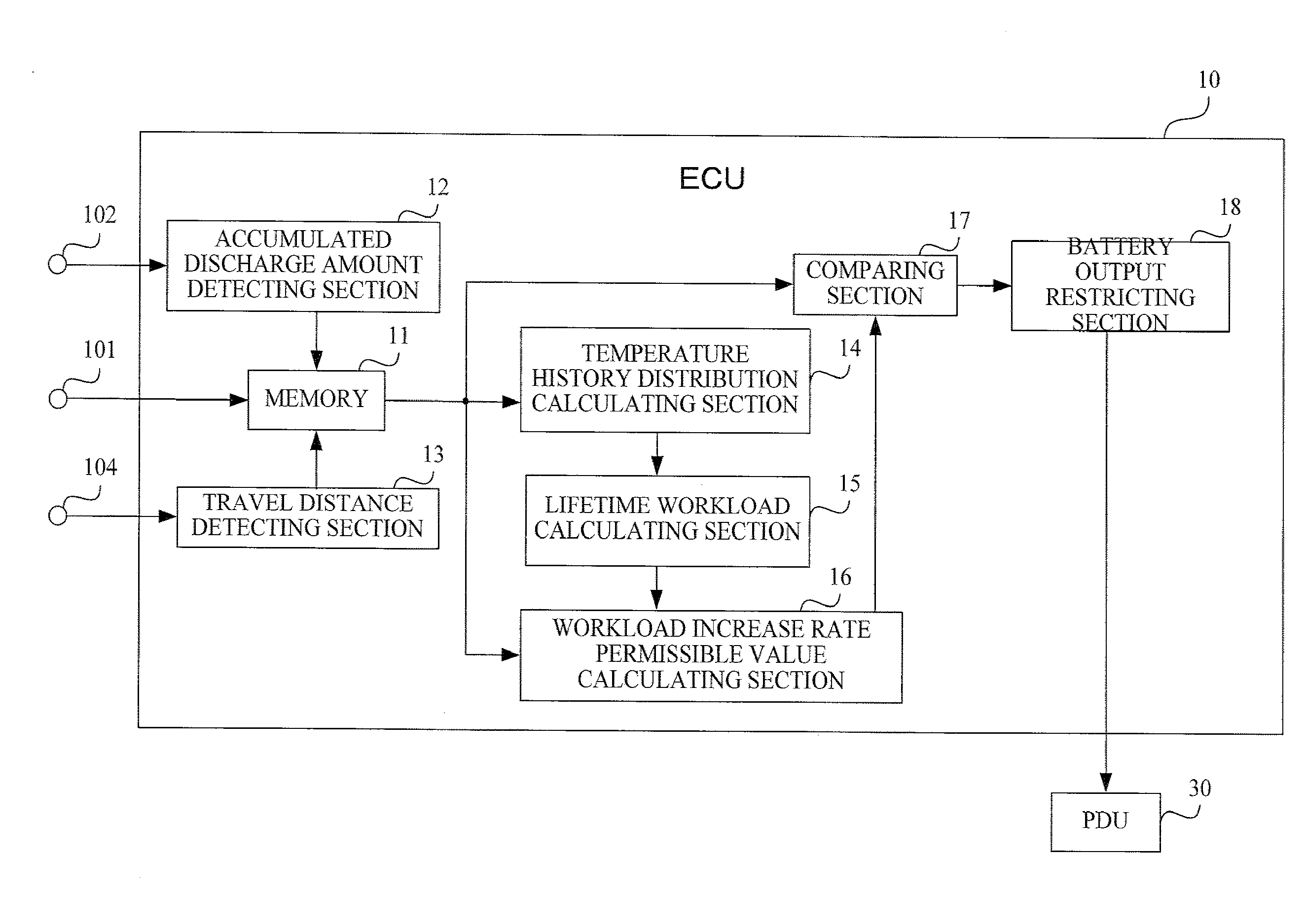
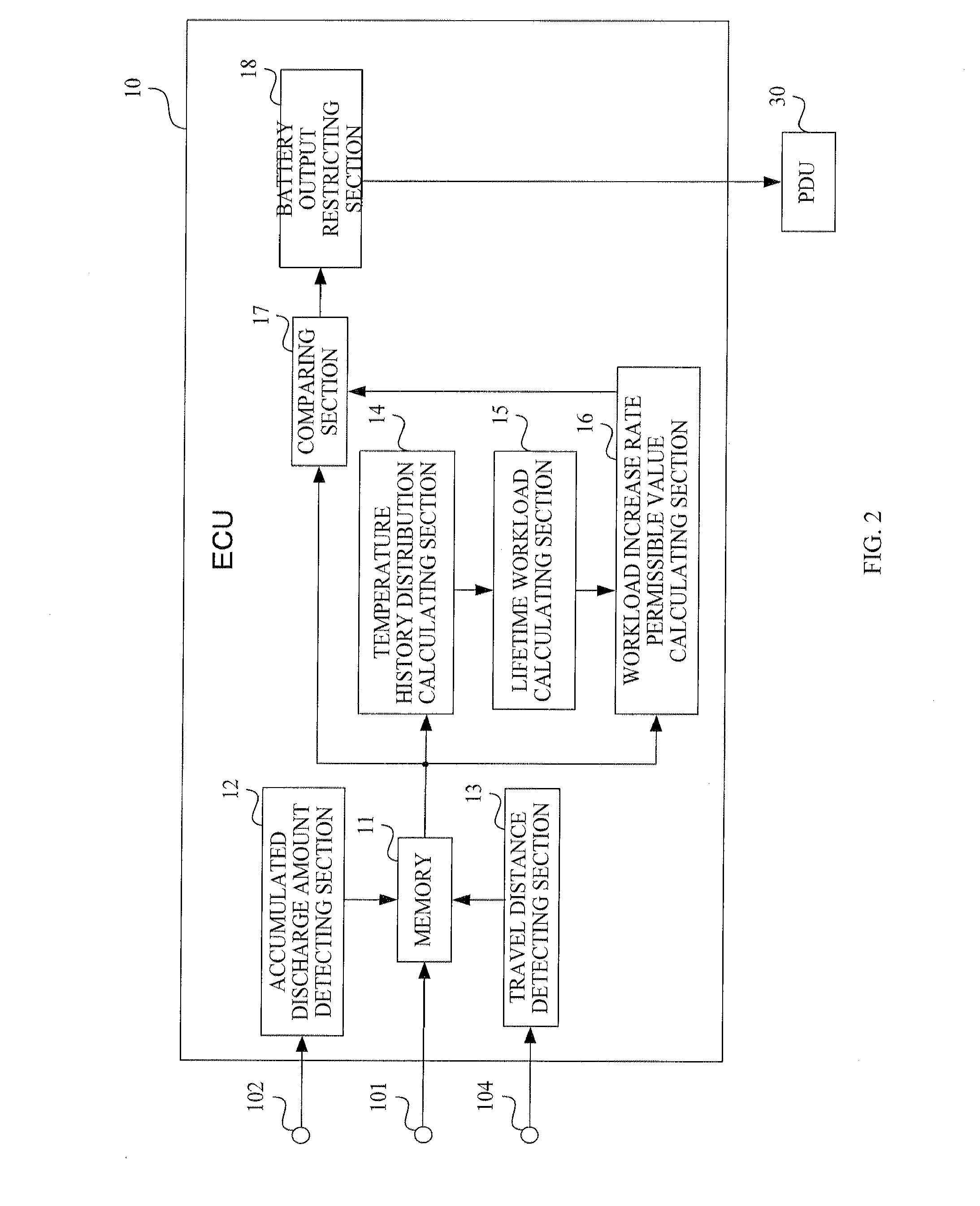
[0033]Further, the vehicle 1 also includes: an electronic control unit (“ECU: Electronic Control Unit”) 10 for controlling the engine 2 and the electric ...

Example

Second Embodiment

[0082]Hereinafter, a second embodiment of the present invention will be described. In this regard, a vehicle according to the second embodiment has a configuration similar to that of the vehicle 1 according to the first embodiment, and an electronic control unit according to the second embodiment also has a configuration similar to that of the electronic control unit 10 according to the first embodiment. Therefore, the illustration and explanation of the vehicle and the electronic control unit are omitted.

[0083]In the present embodiment, control thereof is different from that in the first embodiment in that the temperature history distribution of the battery 20 during one DC is not used, but temperature history distribution of the battery 20 during lifelong drive of the vehicle 1 is used. When an output of the battery 20 is restricted using the temperature history distribution of the battery 20 during the lifelong drive, in order to inhibit disturbance such as data ...


PUM


Abstract

A battery charge/discharge control apparatus for a vehicle capable of driving an electric motor by a battery is provided. Temperature of the battery is detected, temperature history distribution of the battery after start of temperature detection is calculated, and a lifetime workload of the battery is calculated on the basis of this temperature history distribution of the battery. A permissible value of a workload increase rate indicating a workload to increase per unit distance is calculated on the basis of the lifetime workload of the battery and a travel distance of the vehicle. An actual workload increase rate of the battery is compared with the permissible value of the workload increase rate. In the case where the actual workload increase rate is larger than the permissible value of the workload increase rate, an output is restricted from the output of the battery restricted in a normal driving mode if necessary by a restricted value based upon a difference between the actual workload increase rate and the permissible value of the workload increase rate. This makes it possible to carry out lifetime prolonging control for the battery more accurately by setting up an appropriate charge/discharge permissible amount in accordance with temperature change of the battery in the past.

Description

TECHNICAL FIELD[0001]The present invention relates to a battery charge / discharge control apparatus for controlling charge / discharge of a battery to supply electric power to an electric motor for driving a vehicle, and more specifically, the present invention relates to a battery charge / discharge control apparatus for controlling output and regeneration of the battery in accordance with a battery workload with respect to a travel distance of the vehicle.BACKGROUND ART[0002]Heretofore, there is a vehicle that mounts thereon a power train, which uses two kinds of power sources including a gasoline or diesel engine that is an internal combustion and an electric motor. Such a power train is called as a hybrid system. This electric motor is driven by electric power supplied from a high voltage battery mounted on the vehicle. For example, in the case where an AC motor is used as the electric motor, DC power outputted from the battery is converted to AC power by means of a circuit such as a...

Claims


Application Information

Patent Timeline
IPC IPC(8): H02J7/00
CPCB60K6/485Y02T10/705B60W20/00B60W2510/246B60W2510/248B60W2530/14G01R31/3679Y02T10/6226B60L11/1857B60L11/1862B60L11/187H01M10/443H01M10/48B60L2260/50H01M2220/20Y02T10/7044Y02T10/7005B60W10/26G01R31/392B60L58/16B60L58/24Y02T10/62Y02T10/70Y02E60/10B60W2510/244B60W2556/10B60W20/13
Inventor OGANE, TAKASHIMARUNO, NAOKIMATSUDA, TSUYOSHIFUJITA, YUJI
Owner HONDA MOTOR CO LTD
Why Eureka
Try Eureka