

Hydrophilic porous layer for fuel cells, gas diffusion electrode and manufacturing method thereof, and membrane electrode assembly
a technology of hydrogen porous layer and fuel cell, which is applied in the manufacture of cell components, final product products, electrochemical generators, etc., can solve the problems of constant humidification of the membrane, poor gas diffusion, and inducing voltage drop, so as to achieve sufficient evaporation area and avoid undesired voltage drop
- Summary
- Abstract
- Description
- Claims
- Application Information
AI Technical Summary
Benefits of technology
Problems solved by technology
Method used
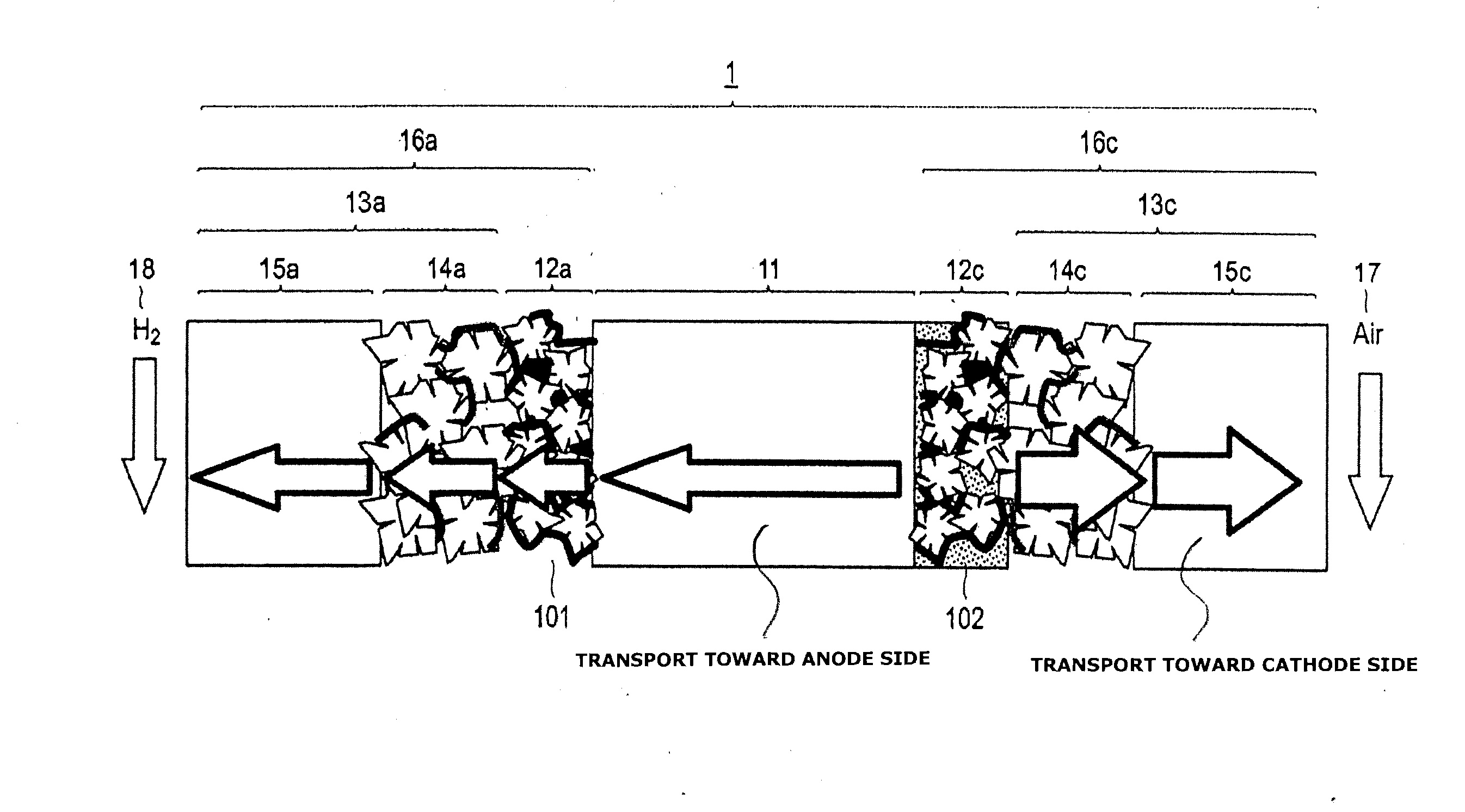
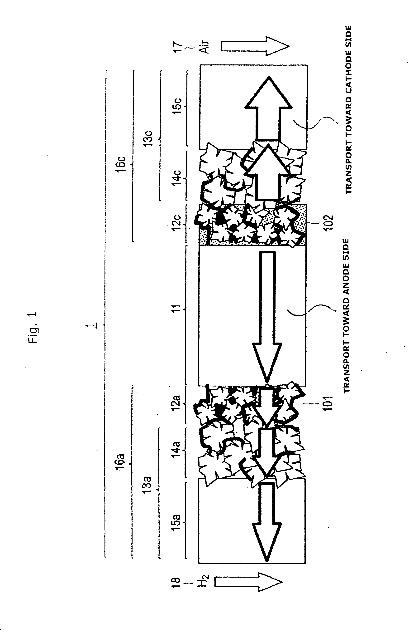
Image

Examples
embodiment
[0221]In the following, steps for producing the hydrophilic porous membrane, the gas diffusion electrode layer and the membrane electrode assembly in the invention will be described as an embodiment. However, the technical range of the invention is not limited to only the following embodiment.
[0222](1) Production Method for the Hydrophilic Porous Membrane, the Gas Diffusion Electrode Layer and the Membrane Electrode Assembly.
[0223]1. Production of Sample-A
[0224]As the electrically conductive material for the ink for the hydrophilic porous layer, carbon powder (Ketchen black EC, (produced by Ketchen Black International Co., Ltd.) was prepared. And as the hydrophilic material, an ionomer dispersant liquid (Nafion (registered trade name) D2020, produced by Dupont) was prepared. Then, these materials were so mixed that the carbon powder and the ionomer have a mass ratio (electrically conductive material / hydrophilic material) being 0.7 and as a solvent and a pore former, a propylene glyc...
PUM
| Property | Measurement | Unit |
|---|---|---|
| mean particle diameter | aaaaa | aaaaa |
| diameter | aaaaa | aaaaa |
| diameter | aaaaa | aaaaa |
Abstract
Description
Claims
Application Information