Glass substrate-holding tool

a technology of holding tools and glass substrates, which is applied in the direction of printing tools, instruments, manufacturing tools, etc., can solve the problems of glass substrate holding tools, dusting, and scratches on film-forming surfaces, and achieve the effect of preventing dusting and preventing dusting

Inactive Publication Date: 2012-04-26
ASAHI GLASS CO LTD
View PDF1 Cites 378 Cited by
  • Summary
  • Abstract
  • Description
  • Claims
  • Application Information

AI Technical Summary

Benefits of technology

[0039]The glass substrate-holding tool of the present invention catches and holds only the rear surface of the glass substrate, whereby it is possible to avoid scratching to the deposition surface of the glass substrate and dusting thereby caused. Further, in the production of an EUV mask blank, a mechanism to directly clamp the substrate such as a mechanical chuck, is not present, whereby it is possible to prevent dusting from the glass substrate-holding tool itself during the film deposition.
[0040]The glass substrate-holding tool of the present invention catches and holds only the periphery of the rear surface of the glass substrate, whereby it is possible to avoid deposition of foreign substances or scratching to the center portion of the rear surface of the glass substrate (e.g. in the case of a substrate of 152.4 mm×152.4 mm, to a region of 146 mm×146 mm at the center portion of the substrate).
[0041]The glass substrate-holding tool of the present invention does not require application of high voltage to produce a strong electrostatic power like an electrostatic chuck and catches and holds a glass substrate by van der Waals forces at the catching portion and electrostatic attraction (when the catching portion is positively-charged), whereby there will be no possibility of a problem of attracting foreign substances by a residual electric charge or leaking electric field which may happen when a glass substrate is catched and held by an electrostatic chuck.
[0042]According to a method for producing an EUV mask blank and a method for producing a reflective mask of the present invention, wherein the glass substrate-holding tool of the present invention is used as a tool for holding a glass substrate, it is possible to produce an EUV mask blank and a reflective mask, which are free from scratches or foreign substances at the center portion of the rear surface.

Problems solved by technology

However, such glass substrate-holding tools had the following problems.
In the former case, the surface of the glass substrate on which the multilayer reflection film or the absorptive layer is formed is clamped, thus leading to a problem such that scratches are likely to be formed on the film-forming surface, or dusting is likely to be caused by such scratching.
On the other hand, in the case of the latter, the mechanical chuck is usually larger than the glass substrate in the side surface direction, and during the forming of the multilayer reflective film or the absorptive layer, the amount of film deposition on the chuck itself is likely to increase, which is likely to cause dusting.
However, by the contact of the center portion of the rear surface (the rear surface to the film-deposition surface) of the glass substrate with the catching and holding surface of the electrostatic chuck, foreign substances are likely to deposit on the center portion, or scratches are likely to be formed at the center portion.
Especially when the electrostatic chuck is used for holding, a problem is likely to occur such that foreign substances are attracted by the residual electric charge or leaking electric field.
However, in the case of substrate having a low dielectric constant and electrical conductivity like a glass substrate, it is required to apply a high voltage in order to obtain a chuck force at a level equivalent in the case of a silicon wafer, whereby there is a possible danger of insulation breakdown.
If foreign substances, particularly foreign substances with a size of at least 200 nm, are deposited on the center portion of the rear surface of the glass substrate, an electroconductive film on the rear surface is likely to be damaged.
Further, by such a damage of the electroconductive film on the rear surface, new foreign substances are likely to be formed.
In a case where foreign substances are deposited on electrode portions of the electrostatic charge in the film deposition apparatus, when such a film deposition apparatus is used next time, the electrode portions in such a state that foreign substances are deposited, will be in contact with a rear surface electroconductive film formed on the rear surface of a fresh glass substrate, such being problematic.
Also at the time of preparing a reflective mask from an EUV mask blank, deposition of foreign substances on the electrode portions of the electrostatic chuck in the exposure apparatus, is problematic in that the glass substrate is likely to undergo warpage, and the exposure pattern is likely to be deformed.

Method used


Image

  • Glass substrate-holding tool
  • Glass substrate-holding tool
  • Glass substrate-holding tool

Examples


example 1

[0179]In Example 1, a glass substrate-holding tool 100B shown in FIG. 5 is prepared. By a silicone resin, a catching portion 20 is formed at the periphery of the base 10 made of aluminum oxide and having a size of 6 inch (152.4 mm) square. The silicone resin used has a catching force F0 per unit surface area of 4 gf / mm2, and the catching portion 20 has a width of 1.5 mm and a height of 1 mm. Accordingly, the contact area S of the catching portion 20 to the glass substrate is about 902 mm2. Further, from the above formula (2), the substrate-catching force F by the catching portion 20 is about 3,608 gf.

[0180]At four corners of the base 10, circular lifting up mechanisms 30 having a diameter of 1 mm are provided to release the glass substrate 200 from the catching portion 20.

[0181]By means of the glass substrate-holding tool 100B thus prepared, a glass substrate for an EUV mask blank is catched and held. For the glass substrate 200, a SiO2—TiO2 glass substrate having a size of 6 inch (...

example 2

[0184]In Example 2, a glass substrate-holding tool 100C shown in FIG. 6 is prepared. A glass substrate-holding tool is prepared in the same procedure as in Example 1 except that a base 10 wherein grooves 40 with a width of 19 mm are provided to let arms 50 for transporting a substrate pass therethrough. Accordingly, the contact area S of the catching portion 20 to the glass substrate is about 788 mm2, and the substrate-catching force F by the catching portion 20 is about 3,152 gf.

[0185]In the same procedure as in Example 1, catching and holding of a glass substrate are carried out, and the number of defects of at least 200 nm, increased after the catching and holding is evaluated. The result is 0 like in Example 1.

[0186]In the same procedure as above, the catching and holding of the glass substrate are repeated ten times, but no displacement or falling of the glass substrate from the base 10 of the catching and holding tool 100C is observed, and no deterioration of the catching rete...

example 3

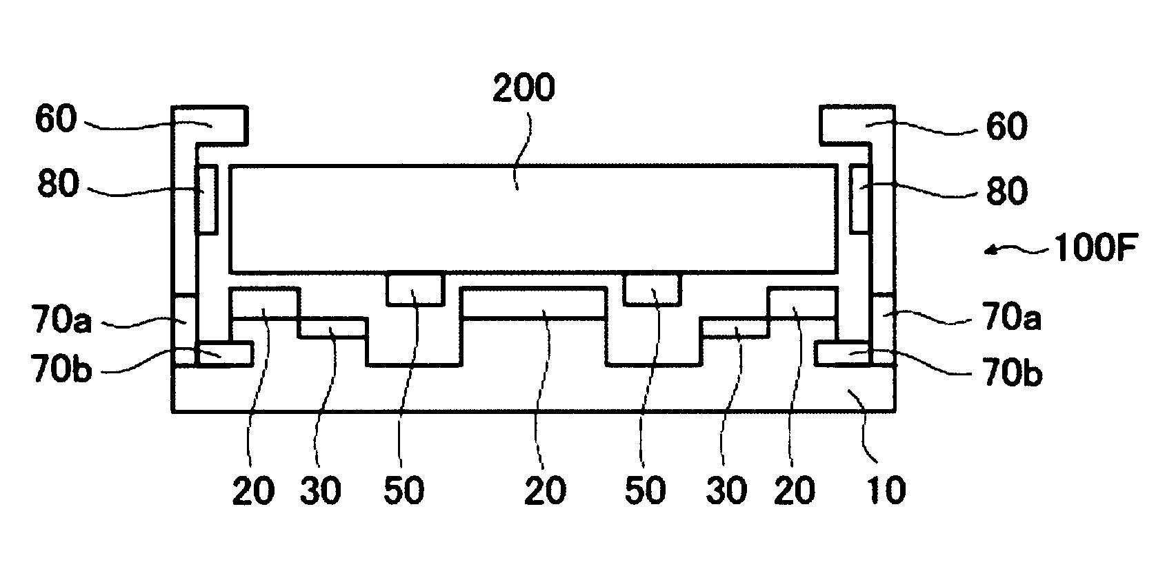
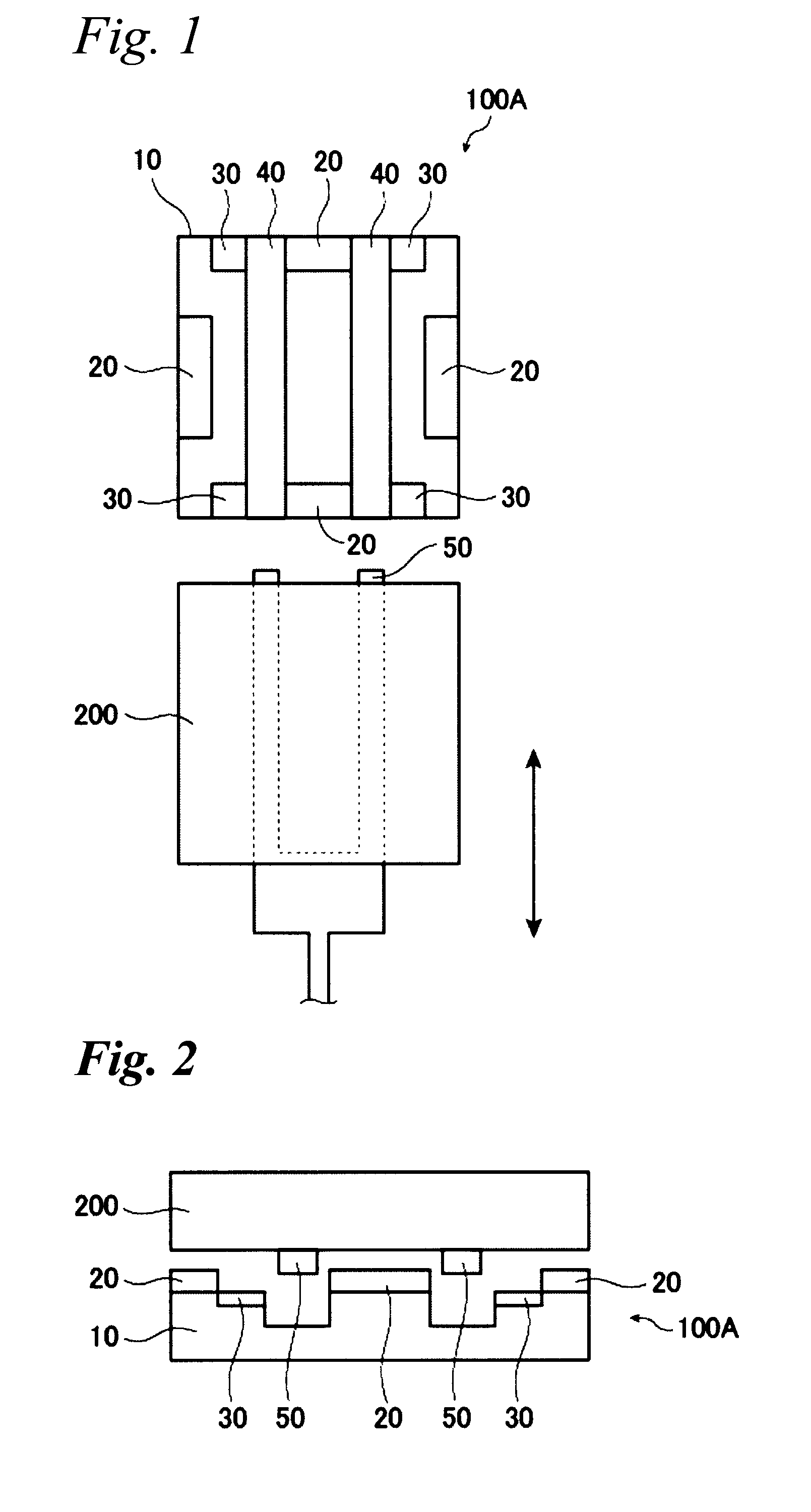
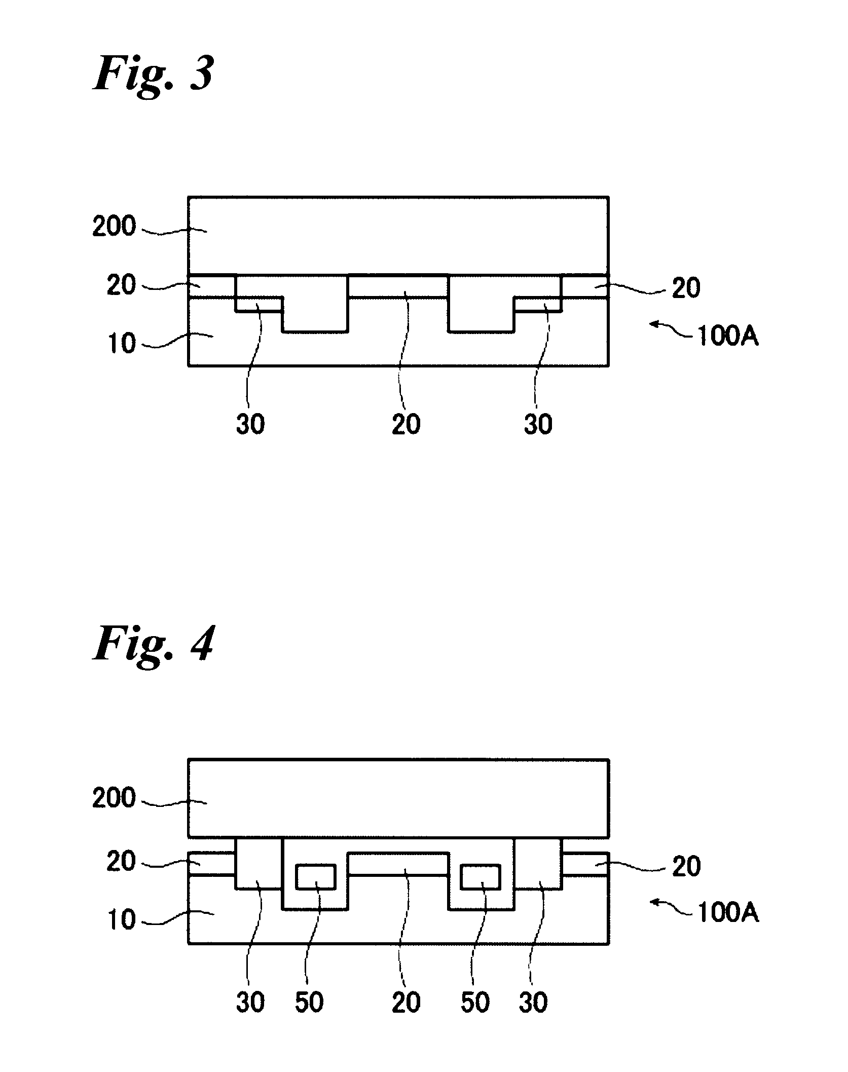
[0187]In Example 3, a glass substrate-holding tool 100A shown in FIGS. 1 to 4 is prepared. In the same manner as in Example 2, by using a base 10 wherein grooves 40 are provided to let arms for transporting a substrate pass therethrough, by the same silicone resin as in Examples 1 and 2, a catching portion 20 is formed at a part of the periphery of the base 10. The width of the catching portion 20 is made to be 2 mm, the height is made to be 1 mm, and the total contact area S of the catching portion 20 to the glass substrate is about 760 mm2. Near the grooves 40, lifting up mechanisms 30 are provided. The substrate-catching force F by the catching portion 20 becomes about 3,040 gf.

[0188]In the same procedure as in Examples 1 and 2, the catching and holding of a glass substrate are carried out, and the number of defects of at least 200 nm increased after the catching and holding is evaluated, and the result is 0 like in Examples 1 and 2.

[0189]In the same procedure as above, the catch...


PUM

PropertyMeasurementUnit
contact areaaaaaaaaaaa
diametersaaaaaaaaaa
diametersaaaaaaaaaa

Abstract

To provide a glass substrate-holding tool which is capable of avoiding scratching to the deposition surface of a glass substrate and dusting thereby caused as well as scratching and deposition of foreign substances at a center portion of the rear surface of the substrate and which is capable of suppressing dusting from the holding tool itself at the time of forming a multi-layered reflection film and an absorptive layer.
A glass substrate-holding tool having, formed on a surface of a flat base, a catching portion for catching and holding by van der Waals forces, wherein the catching portion is in contact with only the periphery of the glass substrate.

Description

FIELD OF THE INVENTION[0001]The present invention relates to a glass substrate-holding tool. The glass substrate-holding tool of the present invention is useful for holding a glass substrate during the production of a reflective mask blank for EUV (Extreme Ultra Violet) lithography (hereinafter referred to as “EUV mask blank” in this specification) to be used for e.g. the production of semiconductors, during a mask patterning process at the time of preparing a reflective mask from an EUV mask blank, or during handling of a reflective mask at the time of exposure in EUV lithography.[0002]Further, the present invention relates to a method for producing an EUV mask blank, a method for producing a reflective mask and a method for producing a semiconductor integrated circuit, employing the glass substrate-holding tool of the present invention.DISCUSSION OF BACKGROUND[0003]In the semiconductor industry, a photolithography method using visible light or ultraviolet light has been employed a...

Claims


Application Information

Patent Timeline
Patent Type & Authority Applications(United States)
IPC IPC(8): G03F1/00B23Q3/00G03F7/20
CPCG03F1/24H01L21/6831H01L21/67742G03F7/70741
Inventor KAGEYAMA, JUNICHI
Owner ASAHI GLASS CO LTD
Why Eureka
Try Eureka