
System and apparatus to monitor biopacemaker maturation

Active Publication Date: 2012-05-03
MEDTRONIC INC
View PDF5 Cites 6 Cited by
  • Summary
  • Abstract
  • Description
  • Claims
  • Application Information

AI Technical Summary

Benefits of technology

[0006]The present invention includes a method of monitoring the functional effect of an intervention effecting cardiac pacing, the method including halting artificial pacing provided by an implantable electronic pulse generator to a heart subject to an intervention ef

Problems solved by technology

While effectively improving the lives of many patients, such implantable pacemakers have certain technical limitations.
For example, implantable pacemakers rely on a self-contained power source such as a battery and consequently have a limited lifetime before the power source is in need of replacement.
In addition, implantable pacemaker batteries are large and are usually the bulkiest pacemaker component.
Also, implantable pacemakers have very limited or no capacity for directly responding to the body's endogenous signaling the way the SA node responds to such signaling, i.e. by a modulation of the heart rate relative to the physiological and emotional state (e.g. sleep, rest, stress, exercise).

Method used


Image

  • System and apparatus to monitor biopacemaker maturation
  • System and apparatus to monitor biopacemaker maturation
  • System and apparatus to monitor biopacemaker maturation

Examples


example 1

Bio-Pacer EGM User Interface Application

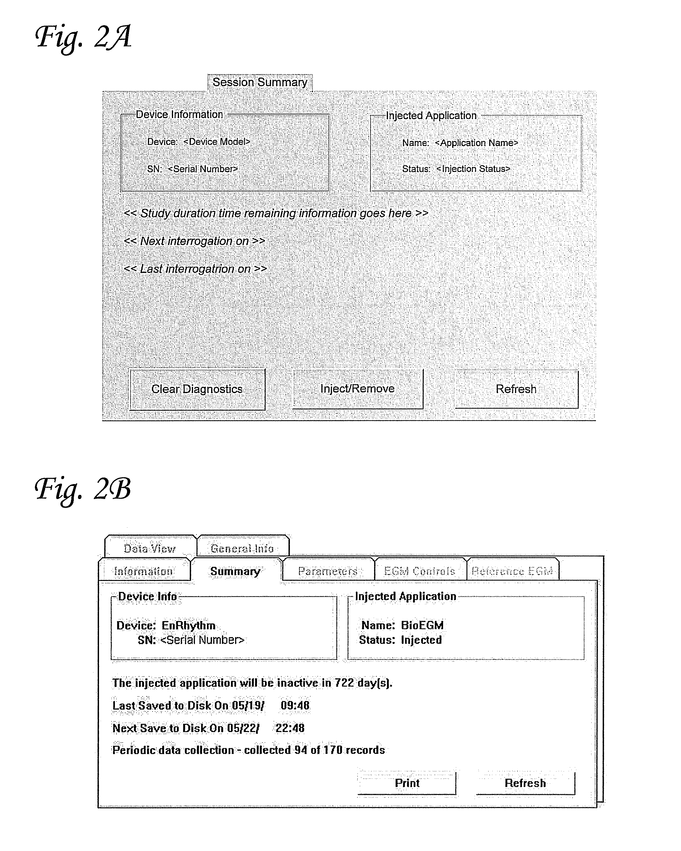
[0108]A Bio-pacemaker EGM system was constructed with the following components; an EnRhythm® pacemaker, Bio-pacemaker EGM RAMware, and a 2090 Programming system. Functional responsibilities of the EnRhythm device relevant to the application of Bio-pacemaker EGM include pacing (providing all pacing output and timing functions for bradycardia pacing), detection (providing detection of sustained tachyarrhythmias, SVT discrimination, and the basic RR Median value), diagnostics (providing detailed data on sustained episodes), and RAMware (providing the existing RAMware hooks used to manipulate pacing functionality and add diagnostics applicable to Biopacemaker EGM). Functional responsibilities of RAMware relevant to the application of Bio-pacemaker EGM include EGM diagnostics, such as the capabilities to capture additional sinus / intrinsic rhythm EGM based on user programmer parameters and to control pacing rate. Functional responsibilities of the 2...

example 2

Creating a Ventricular Biopacemaker

[0169]In this example, a gene construct of wild-type HCN4 packaged in a bicistronic adenoviral vector co-expressing GFP demonstrated ventricular biological pacemaker. Briefly, in an AV-blocked canine, a bicistronic adenoviral vector construct (Ad-HCN4-IRES-eGFP) encoding human wild-type HCN4 and eGFP was injected at the apex of the left ventricle (LV). The reporter gene construct Ad-eGFP was also injected at the base of the LV. Periodic in-life data showed ventricular escape rate at 136.2 ±7.0 bpm on Day 3, and the maximum rate achieved was 159.4 bpm at Day 3.4. The similarities in the electrogram morphologies of paced references recorded at the injection procedure and periodic recordings from BioEGM suggest that the origin of activation is at or near the injection sites in the left ventricle. A terminal procedure was performed on Day 7 during which activation mapping confirmed activation from the injection site in the LV apex. Histological analysi...

example 3

Creating Atrial and Ventricular Biological Pacemakers

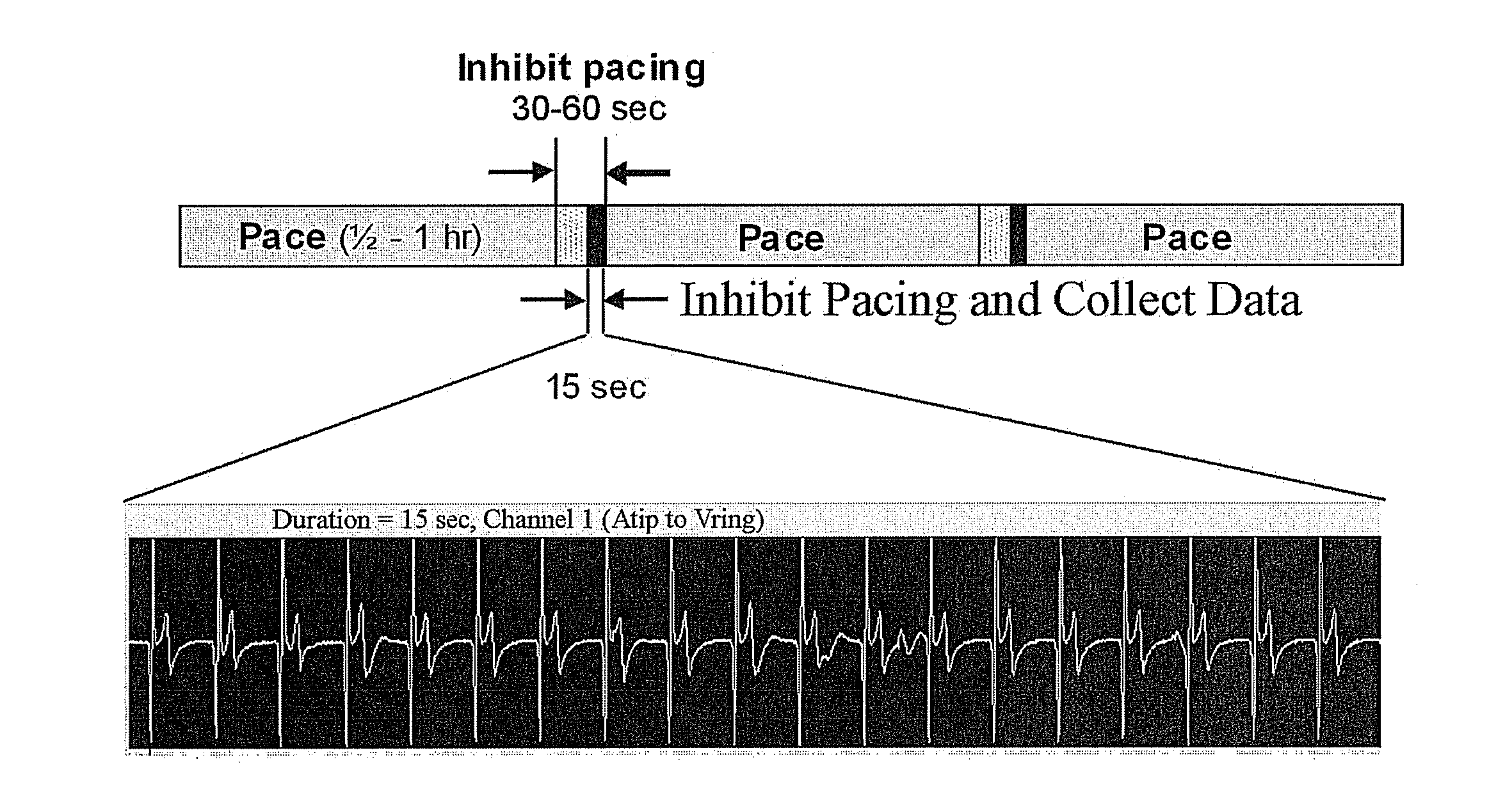
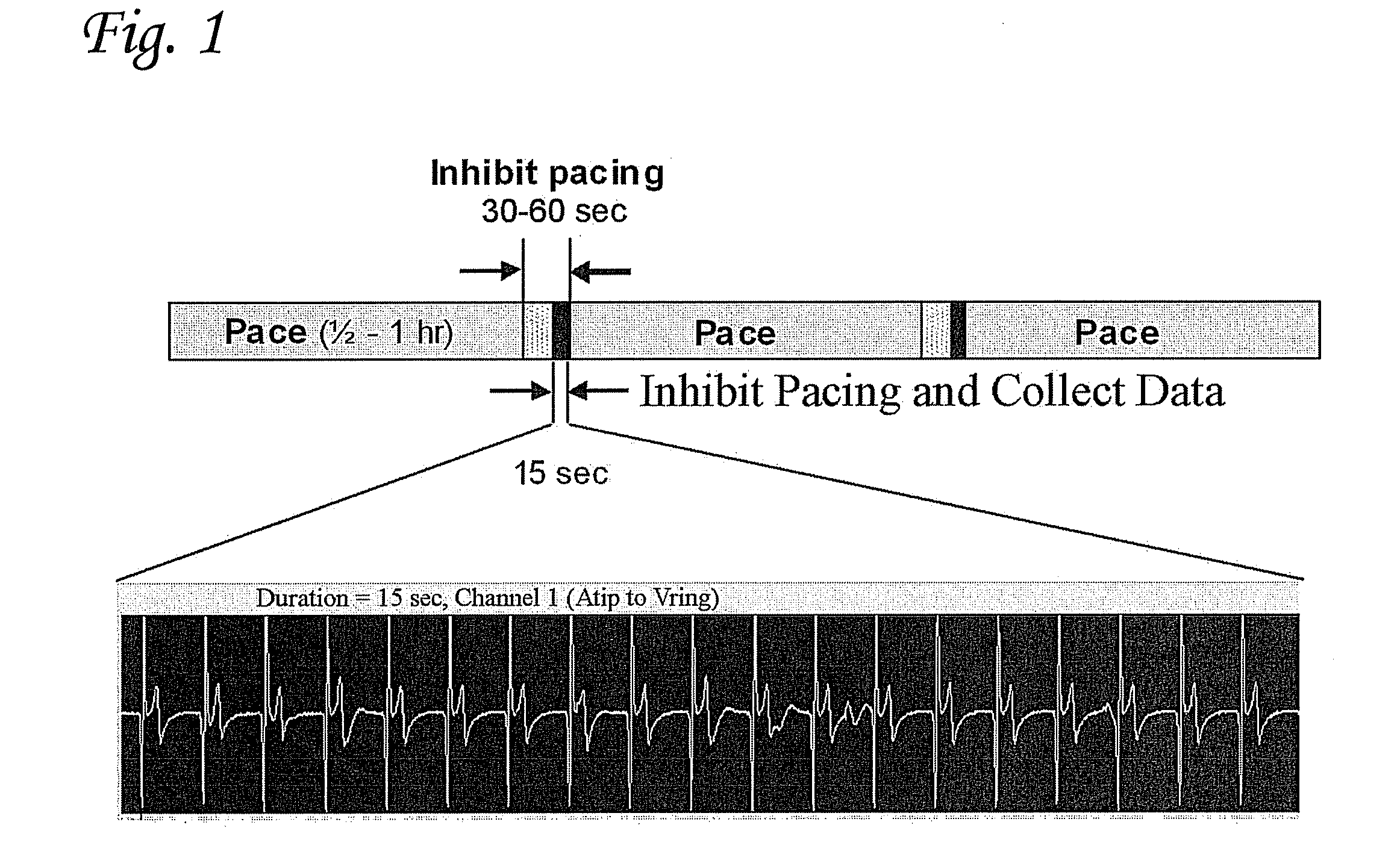
[0187]In this example an adenoviral vector encoding a fused construct of truncated HCN4 and eGFP (Ad-HCN4m-eGFP) was injected at the apex of the left ventricle (LV) and at a site in the left atrium (LA) an AV-blocked canine. Leads were implanted at the injection sites as well as in the right atrium and right ventricle, and atrial leads were connected to a modified implantable pulse generator (IPG) and ventricular leads to a second modified IPG (FIG. 14A). At implant, reference electrograms of the escape rhythm and pacing from each injection site were recorded on the IPGs; and for one week, periodic electrograms using two lead vectors were recorded for 15 seconds every 0.5 to 2 hours (FIG. 14B). The periodic data showed isolated beats and short, intermittent runs of left ventricular activation, as well as isolated left atrial beats. At both awake monitors and the terminal procedure, more sustained left ventricular activation was el...


PUM


Abstract

The present invention includes systems, devices, and methods relating to the monitoring of the functional maturation of biological interventions effecting cardiac pacing.

Description

BACKGROUND[0001]Cardiac contraction in a healthy human heart is initiated by spontaneous excitation of the sinoatrial (“SA”) node, which is located in the right atrium. The electric impulse generated by the SA node travels to the atrioventricular (“AV”) node where it is transmitted to the bundle of His and to the Purkinje network. The fibers in the Purkinje network branch out in many directions to facilitate coordinated contraction of the left and right ventricles, thus providing natural pacing. In some disease states, the heart loses some of its natural capacity to pace properly. Such dysfunction is commonly treated by implanting a pacemaking device that generates an electronic pulse.[0002]While effectively improving the lives of many patients, such implantable pacemakers have certain technical limitations. For example, implantable pacemakers rely on a self-contained power source such as a battery and consequently have a limited lifetime before the power source is in need of replac...

Claims


Application Information

Patent Timeline
IPC IPC(8): A61N1/37
CPCA61K48/005G16H15/00A61N1/3702A61N1/37247G06F19/3481A61B5/686A61B5/021A61B5/026A61B5/0468A61B5/14503A61B5/14542A61B5/4848A61B5/7232G16H40/63A61N1/362A61N1/3629A61B5/364G16H20/30G16H40/67
Inventor SHARMA, VINODJAYE, DEBORAH A.SIGG, DANIEL
Owner MEDTRONIC INC
Learn More