Transmission electron microscopy for imaging live cells

a technology live cells, applied in the field of transmission electron microscopy, can solve the problems of limited spatial resolution of diffraction, inability to resolve on a molecular level, and limited technique resolution of live cells, and require special fluorescent labels

Active Publication Date: 2012-05-17
DE JONGE VILIJA +2
View PDF0 Cites 68 Cited by
  • Summary
  • Abstract
  • Description
  • Claims
  • Application Information

AI Technical Summary

Benefits of technology

[0019]In one embodiment, the method further includes the steps of, at a time interval after the recording step: (a) exposing the cell a second electron beam with a second electron dosage, and (b) recording a second image of the cell formed by the second electron beam, thereby obtaining dynamic information about the cell. The second electron dosage is sufficiently low such that the second electron beam does not cause damage to the cell, thereby obtaining dynamic information about the cell.
[0020]In one embodiment, the method further includes the steps of, after the placing step and prior to the exposing step, or after the recording step: (a) exposing the cell to a light beam, and (b) recording a light microscopy image of the cell formed by the light beam. The light beam has an intensity that is sufficiently low such that the light beam does not cause damage to the cell.

Problems solved by technology

However, light microscopy has a diffraction limited spatial resolution of at most 200 nm, such that processes cannot be resolved on a molecular level.
But those techniques still have a limited resolution on live cells and require special fluorescent labels.
Therefore, a heretofore unaddressed need exists in the art to address the aforementioned deficiencies and inadequacies.

Method used


Image

  • Transmission electron microscopy for imaging live cells
  • Transmission electron microscopy for imaging live cells
  • Transmission electron microscopy for imaging live cells

Examples


example 1

[0092]Microfluidic Chamber with Electron Transparent Windows

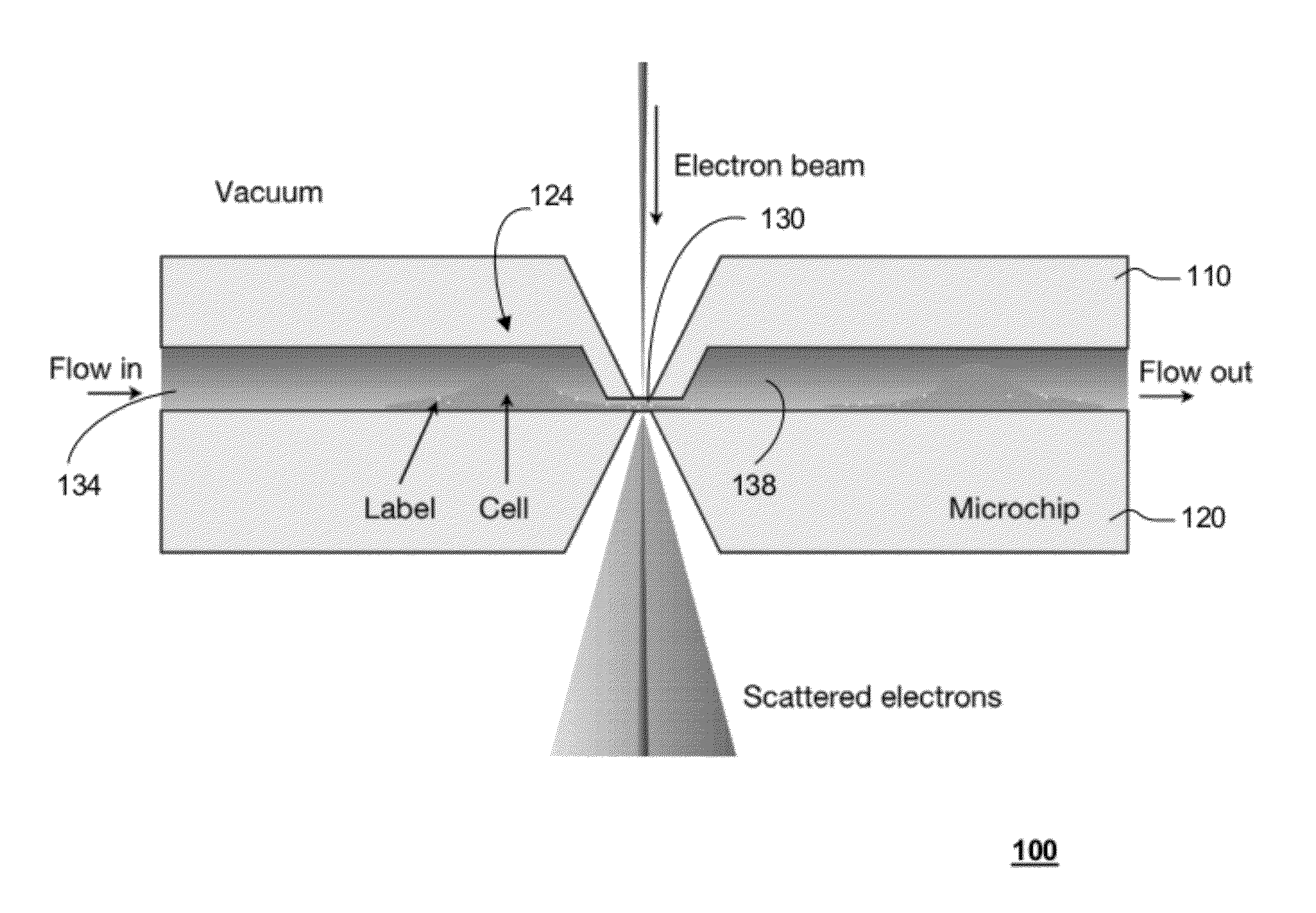
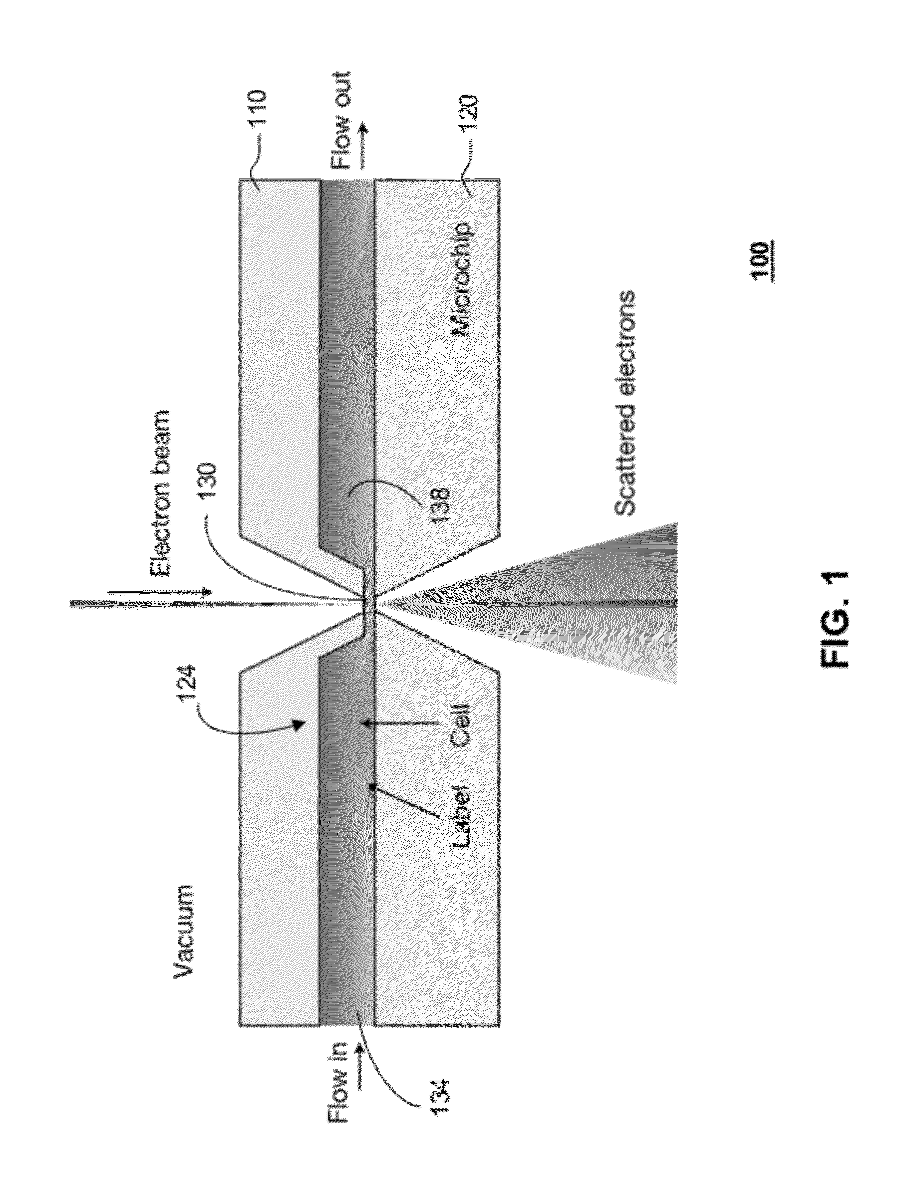
[0093]According to one embodiment of the present disclosure, live cells in liquid are enclosed in a microfluidic chamber shown schematically in FIG. 1. This enclosure is placed in a vacuum of a TEM. The bodies of the cells grow in the two larger sub-chambers, while thin regions of the cell grow into and through a thin sub-chamber. The electron beam propagates through the thin sub-chamber. The thickness of the thin sub-chamber can be adjusted to optimize for a particular experiment. For TEM imaging with phase contrast, or scatter contrast, it is desired to maintain the total sample thickness below one micron, which can be done by setting the thickness of the thin sub-chamber to this value. The TEM can also be operated in scanning mode, so called STEM. Specific high-Z labels can be used to recognize proteins or other molecules. Liquid is flown through the system.

[0094]One key component for live cell TEM is a microfluidic cham...

example 2

[0098]Liquid Specimen Holder Used in Conjunction with a Microfluidic Chamber for Live Cell TEM

[0099]The microfluidic chamber 134 is then placed in a vacuum of a transmission electron microscope using a specimen holder 410 for liquid flow. FIG. 4 shows schematically the specimen holder 410 according to one embodiment of the present disclosure. The specimen holder 410 is of the side-entry type. The specimen at the tip 420 (right end) is connected with liquid tubing to a liquid flow system outside the microscope. An O-ring 414 on the shaft 418 separates the outside air from the vacuum 422 inside the microscope.

[0100]FIG. 5 shows schematically a top view of the slot in the tip 420 of the liquid specimen holder 410, according to one embodiment of the present disclosure. The two microchips 110, 120 are placed on top of each other, with their top surfaces facing each other. They align on their precision made sides via the use of alignment poles 610. Liquid flows from and to liquid ports 61...

example 3

[0102]Live Cell TEM Using a Microfluidic Chamber with Electron Transparent Windows

[0103]In one embodiment, typical experimental cells, for example, eukaryotic cells, are seeded on the microchip 120 with spacer 320. The surface 324 of the microchips 120 is made hydrophilic, for example, by plasma cleaning, and the cell adherence may be enhanced by coating with poly-L-lysine. Prior to poly-L-lysine coating, a layer of water repellant may be applied to the SU8 wall, and also to the area enclosed by the SU8, such that cells preferentially grow in the area over the silicon nitride window. Other chemicals may be used as well for this purpose. Cells are seeded locally by micropipetting, only at one side of the silicon nitride window 310, such that the cells fit into the larger sub-chamber 134, 138 when the microfluidic chamber 124 is assembled. Various cell types, for example, COS7 cells tend to adhere on surfaces and stretch out, becoming thinner, and forming long flat edges. Also neurons...


PUM


Abstract

In one aspect, the present invention relates to a microfluidic chamber. In one embodiment, the microfluidic chamber has a first sub-chamber and at least one second sub-chamber. The first sub-chamber has a first window and a second window. Both the first window and the second window are transparent to electrons of certain energies. The second window is positioned substantially parallel and opposite to the first window defining a first volume therebetween. The first window and the second window are separated by a distance that is sufficiently small such that an electron beam that enters from the first window can propagate through the first sub-chamber and exit from the second window. The at least one second sub-chamber is in fluid communication with the first sub-chamber and has a second volume that is greater than the first volume of the first sub-chamber.

Description

CROSS-REFERENCE TO RELATED PATENT APPLICATION[0001]This application claims the benefit of U.S. Provisional Application No. 61 / 414,603, entitled “Transmission Electron Microscopy for Imaging Live Cells”, filed on Nov. 17, 2010. The disclosure of the above application is incorporated herein by reference in its entirety.[0002]Some references, which may include patents, patent applications and various publications, are cited and discussed in the description of this disclosure. The citation and / or discussion of such references is provided merely to clarify the description of the present disclosure and is not an admission that any such reference is “prior art” to the disclosure described herein. All references cited and discussed in this specification are incorporated herein by reference in their entireties and to the same extent as if each reference was individually incorporated by reference. In terms of notation, hereinafter, “[n]” represents the nth reference cited in the reference lis...

Claims


Application Information

Patent Timeline
Patent Type & Authority Applications(United States)
IPC IPC(8): H04N7/18
CPCB01L3/502715G01N23/2204G01N23/2251H01J2237/2802H01J2237/2003H01J2237/2004H01J37/20
Inventor DE JONGE, NIELS
Owner DE JONGE VILIJA
Why Eureka
Try Eureka