[0014]One or more embodiments of the invention may be utilized in combination with a double battery
assembly, optionally with dual power electrical tabs and high
impact contacts that ensure that the
motion capture element does not lose electrical contact under high
impact. One or more embodiments of the dual battery embodiments may utilize a two-fold contact that effectively couples two batteries in parallel although they are stacked in what would normally be a series connection. In this manner, extended battery life is enabled without custom designed batteries, e.g., so that off-the-shelf batteries may be utilized.
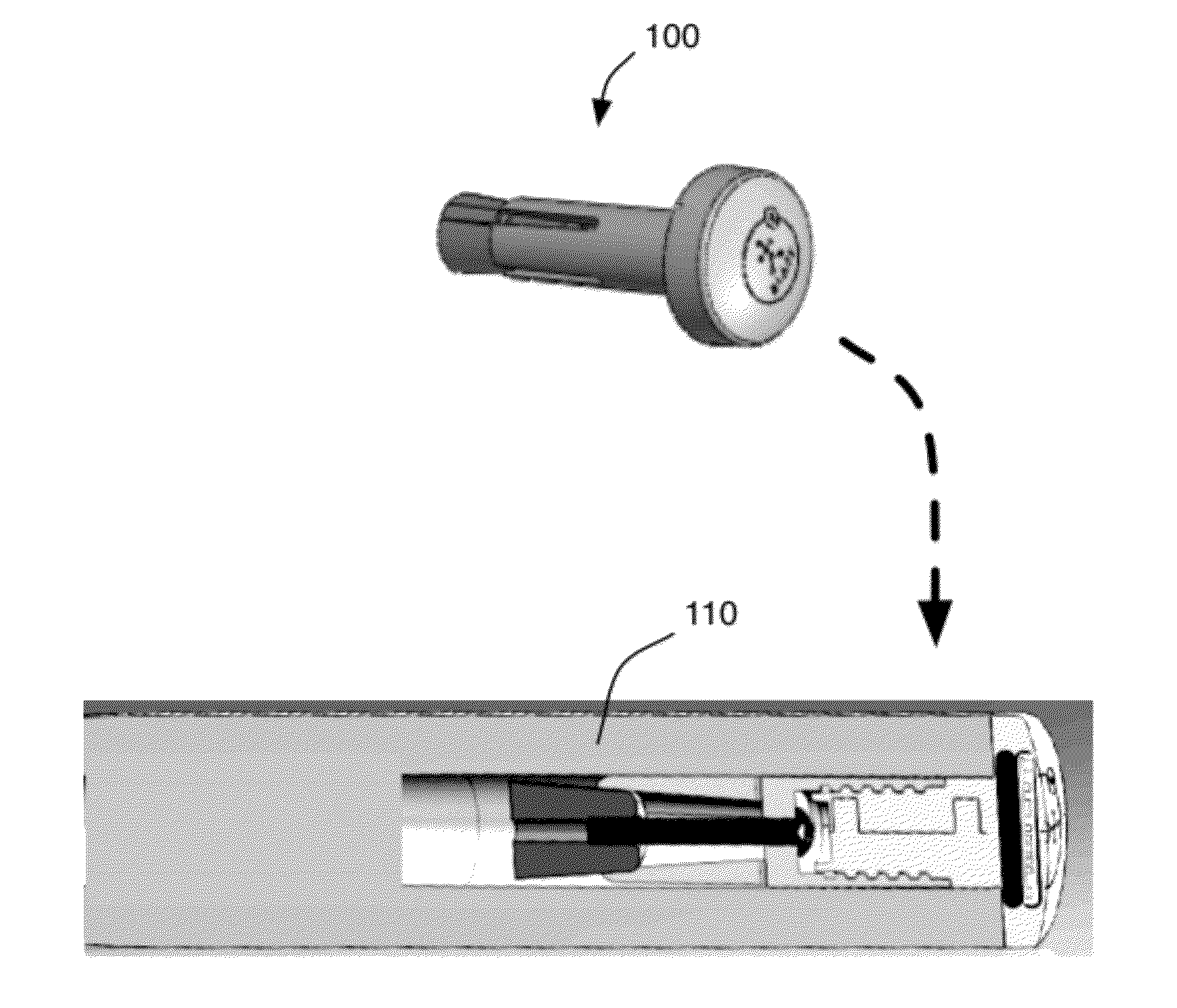
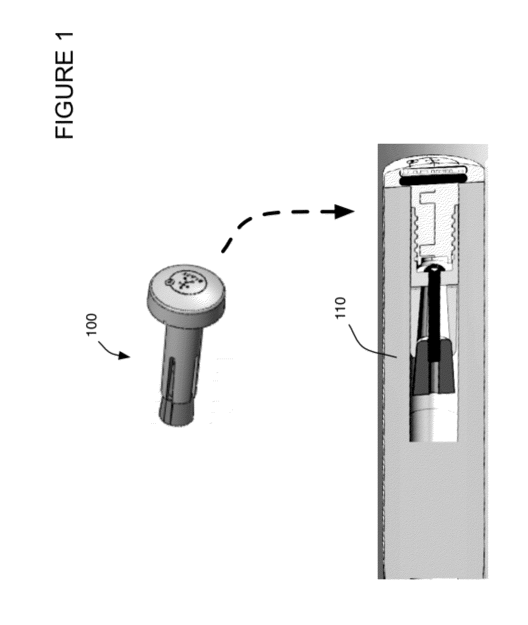
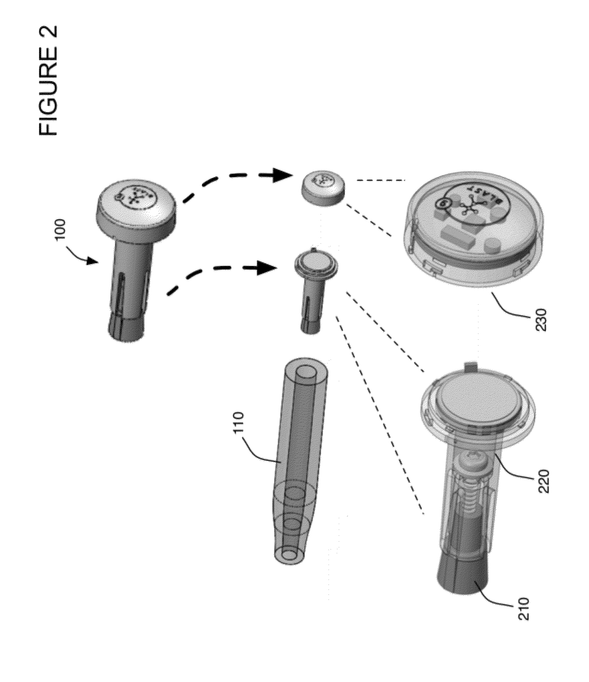
[0015]If the electronics package is installed, then generally a positive battery contact,
printed circuit board (PCB), an insulator or insulative spacer, with negative electrical contact and battery may be installed between the shaft
enclosure and cap. The electronics that may be coupled with the PCB for example may include
active motion capture electronics that are battery powered, passive or active shot count components, for example a passive or active
radio frequency identification (RFID) tag. Embodiments of the electronics may include
motion capture accelerometers and / or gyroscopes and / or an
inertial measurement unit along with
wireless transmitter /
receiver or
transceiver components. The RFID tag enables golf shots for each club associated with a golfer to be counted. Golf shots may optionally be counted via an identifier associated with motion capture electronics on the golf club in conjunction with a mobile computer, for example an IPHONE® equipped with an RFID reader that concentrates the
processing for golf shot counting on the mobile computer instead of on each golf club. Optionally a
wireless antenna may be coupled with the cap or alternatively may be implemented integral to the PCB as desired. One or more embodiments of the invention may also include a
Global Positioning System (GPS) antenna. The
GPS antenna may be mounted on the
printed circuit board or may be located separate from the
printed circuit board. One or more embodiments of the invention may also directly or indirectly communicate with any other sensors coupled with the club including
motion analysis capture elements, strain gauges or any other type of sensor coupled for example with the golf club head. One or more embodiments of the invention may also utilize a battery
coupling that attaches the battery to the shaft
enclosure so that when the cap is removed, the battery does not fall out, unless intended. Embodiments may also utilized spring based
electrical contacts to prevent loss of electrical
conductivity under
high acceleration.
[0016]As previously stated, one or more embodiments may include a weight element, or
slug weight, that is interchangeable with the electronic package in the mount. The electronics package may be removed for example to comply with any sporting rules that do not allow instrumented sporting equipment. For example, USGA Rule 14-3 on Artificial Devices prohibits any “unusual device”, for example under 14-3(b) “For the purpose of gauging or measuring distance”. Any embodiment of the electronics package including a
GPS receiver may thus be removed prior to match play for example and replaced with a weight element to minimize the
weight difference. For example, the weight element may for example weigh close to or the same as the electronics to minimize overall instrumented versus non-instrumented weight differences of the golf club. In addition, a manufacture may provide the mount on each club with a small weight for example, that is removed when the golfer decides to
upgrade the club to include active instrumented electronics or passive shot count elements that weigh the same amount. The net effect on the club dynamics for swing then is negligible. In one embodiment, the plastic portion of the mount weighs 5.7 grams and the battery weighs 3 grams while the screw weighs 1.9 grams. Thus the mounting components have minimal weight and by selecting a weight element of the same weight of the electronics package, or elements within the shaft
enclosure and cap that are replaced by the weight element, the golfer feels no change in club weight when upgrading to an instrumented club.

