Microfluidic devices for reliable on-chip incubation of droplets in delay lines

Inactive Publication Date: 2012-05-17
UNIVERSITY OF STRASBOURG
View PDF4 Cites 32 Cited by
  • Summary
  • Abstract
  • Description
  • Claims
  • Application Information

AI Technical Summary

Benefits of technology

[0011]In yet another embodiment, the microfluidic device may comprise a blocking phase module. The blocking phase module is connected to the device just upstream of the delay line and may consist of a reservoir and fluid flow actuator such as a pump. The blocking phase modulator functions to introduce a blocking phase, or plug. The plug may comprise another phase, such as another aqueous phase, oil phase, or ga

Problems solved by technology

But this configuration is not practical for shorter incubation times. For very short reaction times (e.g., reaction times less than 1 min), short and narrow microfluidic channels have been use

Method used


Image

  • Microfluidic devices for reliable on-chip incubation of droplets in delay lines
  • Microfluidic devices for reliable on-chip incubation of droplets in delay lines
  • Microfluidic devices for reliable on-chip incubation of droplets in delay lines

Examples


examples

1. Fabrication of Microfluidic Devices with Delay Lines

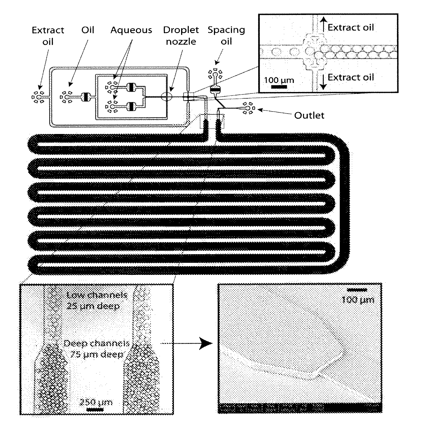
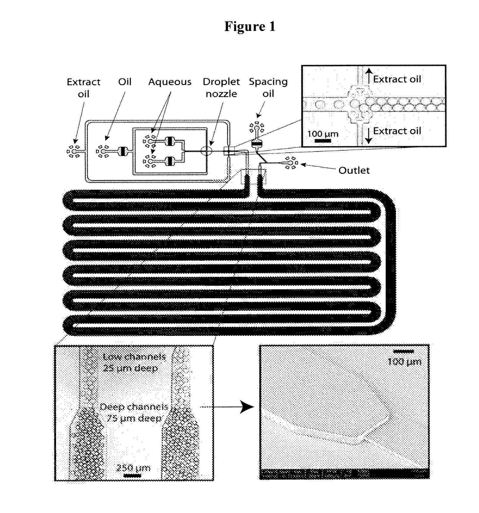
[0066]Soft-lithography in poly(dimethylsiloxane) (PDMS, Sylgard 184, Dow Corning) was used to prepare the devices.21 The molds consisted of SU-8 (Microchem) with two different heights.26 The following procedure was used: A first thinner SU-8 layer (25 μm) was spin coated and exposed to a mask which covers the part of the wafer designated to the deeper structures. After fully developing and baking the structures, a second higher layer of SU-8 was spin coated onto the same wafer. This second layer was exposed and structured by a second mask (delay-line), which was aligned to the lower structures in a mask aligner. Designing the connectors (FIG. 1) in close proximity to each other facilitated the alignment and made it less prone to angle misalignments.

[0067]After casting the mold in PDMS and binding it to a glass side (after activation in an oxygen plasma) the channels were made hydrophobic using a commercial surface coating agent ...


PUM


Abstract

The present invention relates generally to droplet creation, fusion and sorting, and incubation for droplet-based microfluidic assays. More particularly, the present invention relates to delay-lines, which allow incubation of reactions for precise time periods. More particularly, the present invention relates to delay lines for incubations up to three hours, while reducing back-pressure and dispersion in the incubation time due to the unequal speeds with which droplets pass through the delay line.

Description

CROSS-REFERENCE TO RELATED APPLICATIONS[0001]The present application claims the benefit of priority to U.S. Patent Application No. 61 / 103,648, filed Oct. 8, 2008.FIELD OF INVENTION[0002]The present invention relates generally to droplet creation, fusion and sorting, and incubation for droplet-based microfluidic assays. More particularly, the present invention relates to delay-lines, which allow incubation of reactions for precise time periods. More particularly, the present invention relates to delay lines for incubations up three hours, while reducing back-pressure and dispersion in incubation times.BACKGROUND OF THE INVENTION[0003]Compartmentalization of reactions in microdroplets in emulsions has a broad range of applications in chemistry and biochemistry. Each microdroplet functions as an independent microreactor with a volume of between one nanoliter and one femtoliter, which is between 103 and 109 times smaller than the smallest working volumes in a microtitre plate well (1-2 ...

Claims


Application Information

Patent Timeline
IPC IPC(8): B01L3/00
CPCB01F5/061G01N2035/0097B01F5/0688B01F13/0059B01F2005/0621B01F2005/0634B01F2005/0636B01J2219/00596B01J2219/00599B01J2219/0065B01L3/502746B01L3/502761B01L3/502784B01L2200/0652B01L2300/0816B01L2300/087B01L2300/0883B01L2400/0478B01L2400/086C40B50/08G01N35/08G01N2035/00356B01F5/0682B01F25/4317B01F25/431B01F25/431952B01F25/431971B01F25/45B01F25/4521B01F33/30B01L2200/0673
Inventor FRENZ, LUCASBLANK, KERSTIN GODELINDEGRIFFITHS, ANDREW DAVIDBROUZES, ERIC
Owner UNIVERSITY OF STRASBOURG
Why Eureka
Try Eureka