Method and apparatus for reduction of skin effect losses in electrical conductors

a technology of electrical conductors and skin effects, which is applied in the direction of insulated conductors, power cables, cables, etc., can solve the problems of affecting the total system loss, affecting the overall system loss, so as to reduce the skin-effect loss, increase the inductance of the outermost conductor, and reduce the effect of skin-effect losses

Inactive Publication Date: 2012-05-24
PEARSON TIMOTHY RAYMOND
View PDF6 Cites 6 Cited by
  • Summary
  • Abstract
  • Description
  • Claims
  • Application Information

AI Technical Summary

Benefits of technology

[0013]Therefore, it is advantageous to utilize distributed impedance modification of the outermost layers. This can be achieved through the use of the aforementioned magnetic film; such a film can be effectively continuous and constant along the length of the system, preserving the desirable distributed properties of the system. The magnetic film, when applied with specific thickness and distance from the conductor stack, acts to increase the inductance of the outermost conductors while having little or no effect upon the innermost conductors, thus achieving the desired equalization of branch impedances.
[0014]Given the high level of impedance equalization possible with this method, and the fact that the lumped circuit properties of the conductor stack are purposefully left unused, the use of laminated conductors is not required. The present invention will reduce the skin-effect losses even if a solid rectangular conductor is utilized, provided that the magnetic film distance and thickness are properly matched to the physical dimensions of that specific conductor. This should be obvious when the cause of the eddy currents is considered; namely, that a voltage differential exists through the depth of the conductor when the skin effect is occurring. When the skin effect is compensated for, as previously described, this voltage differential is greatly reduced or nonexistent. When the voltage differential does not exist, the insulating films no longer have a purpose and can be removed safely with no effect upon the system.
[0015]Without limiting the scope of the invention, several problems in the prior art and their solution in this invention are discussed herein. With respect to the problem of severe power loss of high frequency signals due to skin effect, a new method has been described to reduce and / or eliminate the skin effect and, thereby, the loss associated with it. With respect to the problem of distortion caused by skin-effect related delay in the inner portions of the conductor, a new method has been described to reduce and / or eliminate the skin effect and, thereby, the distortion associated with it. The present invention also enables high frequency, high magnetic field generation, as it reduces the undesired skin-effect losses without significantly affecting the intensity or distribution of the magnetic field produced outside the wire when high frequency electrical current is applied.

Problems solved by technology

At DC and low frequency, resistive losses in the wire dominate over any impedance caused by the mutual inductance, whereas at high frequency this mutual impedance dominates, giving rise to imbalanced current flow.
Increasing the resistance of the outer conductors would be counterproductive, as the energy flowing therein would be wasted as heat.
Even a relatively small or incomplete equalization of the branch impedances will have a profound effect on total system loss; this is due to the large variation of effective conductor area with respect to branch current imbalance.
While it may be obvious to install discrete inductors in each branch to accomplish the desired equalization, this approach fails for several reasons.
The inductors will, by necessity, contain a relatively small conductor cross-sectional area compared to the main laminated conductor stack, as well as possess considerable internal wire length, thereby causing unacceptable loss.
Other reasons include difficulty of manufacturing, and the conversion of the resultant system from a true distributed impedance to a partially lumped impedance; the latter problem, especially, would severely limit usefulness of the system at high frequencies.

Method used


Image

  • Method and apparatus for reduction of skin effect losses in electrical conductors
  • Method and apparatus for reduction of skin effect losses in electrical conductors
  • Method and apparatus for reduction of skin effect losses in electrical conductors

Examples


Embodiment Construction

[0022]While the design and usage of specific embodiments are discussed below, it should be understood that these discussions do not limit the scope of this invention, and that the broad concepts which are part of this invention may be usable in other specific embodiments which are not discussed below.

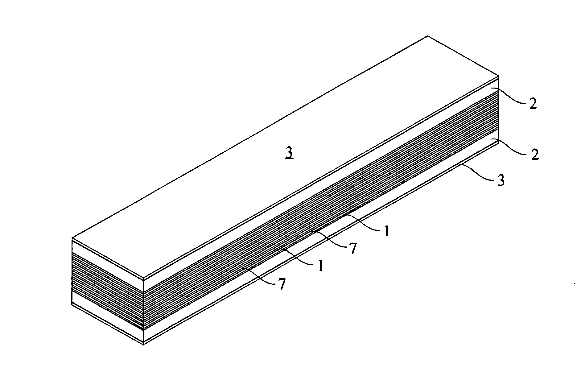
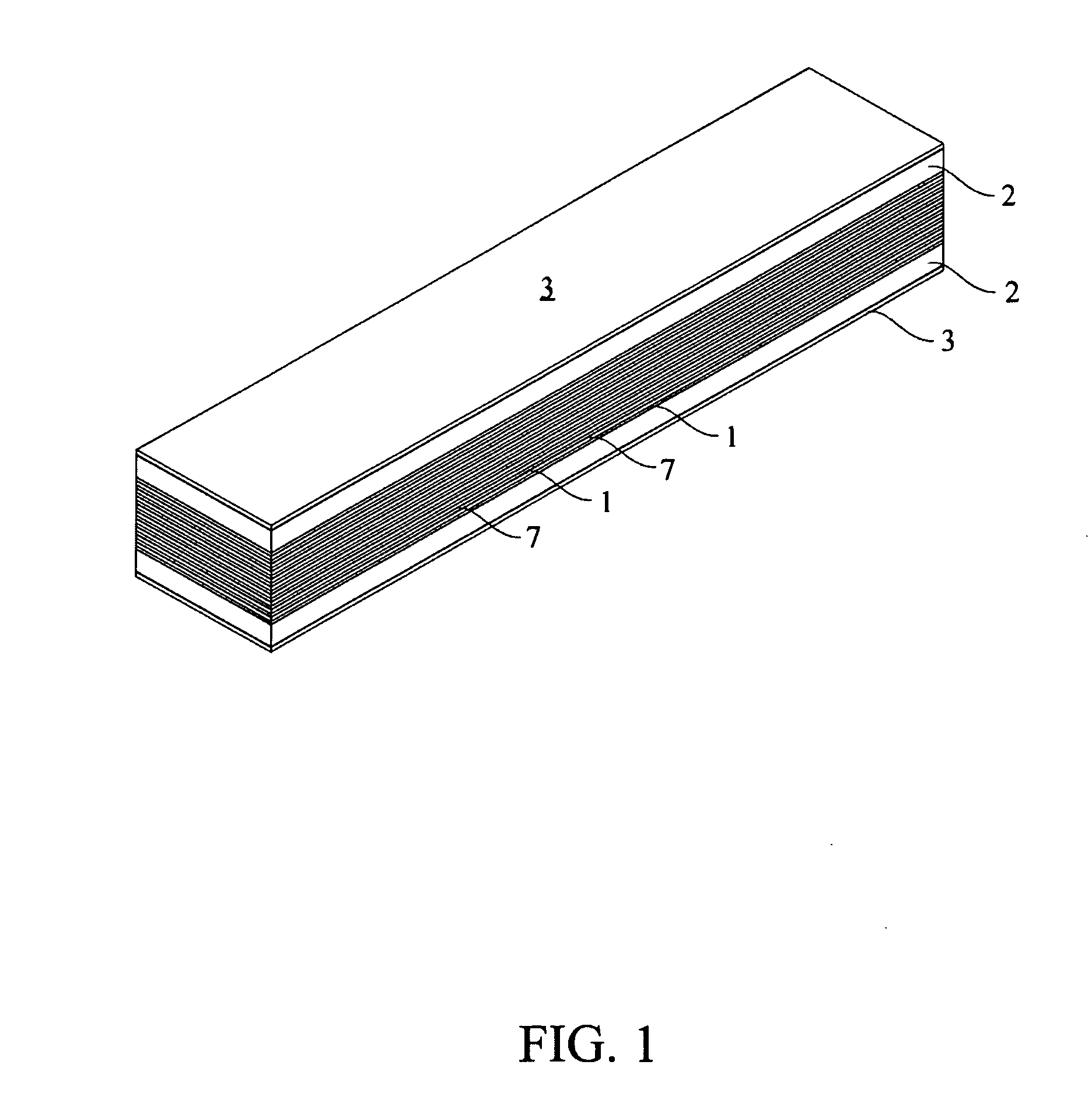
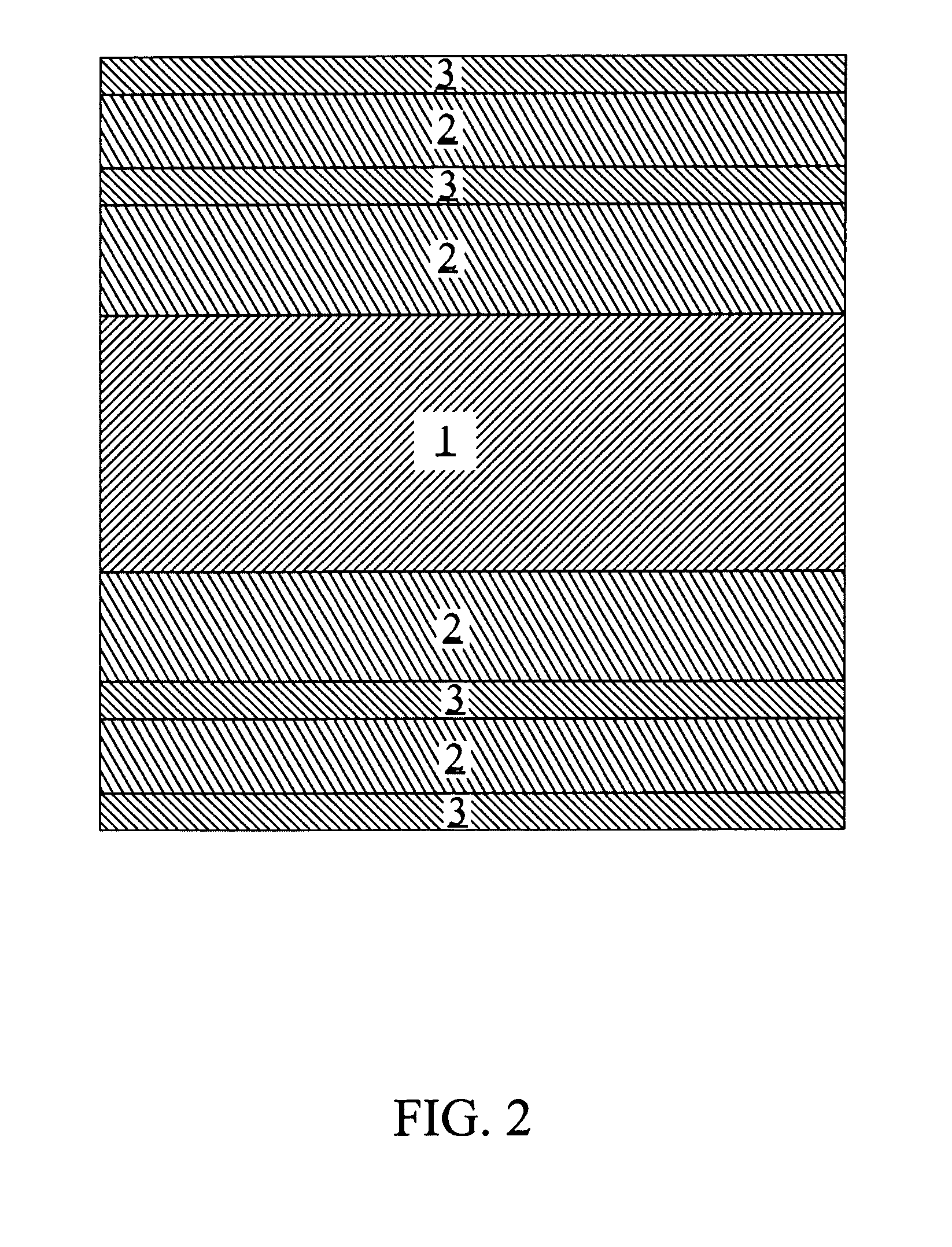
[0023]The skin-effect compensator of the present invention includes a conductor or conductors 1 through which electrical signals are transmitted. Also provided are electrical insulators 2, and a material or materials with a relative permeability greater than one 3, hereinafter referred to as compensators. In one embodiment of the present invention, multiple layers of conductive material 1 are interleaved with multiple insulators 7 in order to isolate each conductor from any adjacent conductors. This embodiment is shown in FIG. 1 of the drawings, and also includes insulators 2 on the top and the bottom of the structure. The insulators 2 act to electrically and physically separate compens...


PUM

PropertyMeasurementUnit
skin depthaaaaaaaaaa
frequenciesaaaaaaaaaa

Abstract

A novel method of reducing the undesired skin effect in electrical conductors is presented. Specific applications including efficient power transmission and high frequency magnetic field generation are discussed, and the advantages over prior art are mentioned. The present invention modifies the inductance of a given conductor with depth into said conductor, allowing the current flowing in the surface of the conductor due to skin effect to diffuse through the remaining conductor area. Inductance is modified in a distributed, continuous fashion via external magnetic structures, ensuring both manufacturability and usability of the resultant conductor. When skin effect inside a conductor is reduced, power loss of transmitted electrical signals is reduced accordingly. Therefore, the present invention represents a significant improvement over prior art.

Description

CROSS-REFERENCE TO RELATED APPLICATIONS[0001]Not ApplicableSTATEMENT REGARDING FEDERALLY SPONSORED RESEARCH OR DEVELOPMENT[0002]Not ApplicableREFERENCE TO SEQUENCE LISTING, A TABLE, OR A COMPUTER PROGRAM LISTING COMPACT DISK APPPENDIX[0003]Not ApplicableBACKGROUND OF THE INVENTION[0004]Without limiting the scope of the invention, its background will be discussed within the framework of general electromagnetics. A significant and persistent problem in high frequency electrical circuits is high loss caused by the skin effect. The skin effect is caused by current crowding near the surface of a conductor, and reduces the effective cross sectional area available for conduction in proportion to the square root of applied signal frequency. At relatively high frequencies, for example those above 1 MHz, the skin depth is less than 0.1 mm. This causes a highly undesirable reduction in effective conductor area, and a corresponding increase in conductor resistive loss. Furthermore, as resistive...

Claims


Application Information

Patent Timeline
Patent Type & Authority Applications(United States)
IPC IPC(8): H01B9/00H01B9/02
CPCH01B7/303
Inventor PEARSON, TIMOTHY RAYMOND
Owner PEARSON TIMOTHY RAYMOND
Why Eureka
Try Eureka