Energy storage and release system

a technology of energy storage and release system, applied in the direction of spring motors, machines/engines, spring motors, etc., can solve the problems of large mechanical clutches and transmissions, complex release and escapement mechanisms, and high electromagnetic clutches, and achieve simple transmission, locking and release of energy, and reduce the manufacturing cost of the technology. , the effect of increasing the useful working life of the technology

Active Publication Date: 2012-05-24
RAYTHEON CO
View PDF4 Cites 5 Cited by
  • Summary
  • Abstract
  • Description
  • Claims
  • Application Information

AI Technical Summary

Benefits of technology

[0014]The energy storage and release technology described herein can provide one or more of the following advantages. The technology advantageously provides a simple transmission, locking, and release of energy without requiring an intermediate device (e.g., a clutch) that disengages the drive train to release the stored energy, thereby reducing the manufacturing cost of the technology and increasing the useful working life of the technology by simplification of the internal mechanisms. The technology advantageously provides for automatic and adjustable levels of energy release and / or can allow for output torque to exceed initial input levels, thereby increasing the useful range of uses for the technology while maintaining a high level of output power.
[0015]The technology advantageously provides a simple transmission of power, a simple locking / retention of stored energy, and / or a simple release of energy (i.e., without the need for a clutch), thereby reducing the number of moving parts which decreases break-downs the technology and increases the useful span of the technology. The technology advantageously can provide an instantaneous recovery to restart energy storing cycle, thereby increasing the usage rate for the technology and decreasing the cost per energy release. The technology can advantageously provide an adjustable release and / or an automatic release, thereby increasing the adaptability of the technology by enabling the technology to work with and as part of different machines (e.g., robot, factory machine, etc.). The technology can advantageously provide a parallel stacking of torsion springs for increased torque load, thereby increasing the effective energy output range of the technology while keeping the input energy at a steady state. The technology can advantageously provide an intelligent and programmable release of the stored energy, thereby increasing the adaptability of the technology to work with and as part of different machines.

Problems solved by technology

Such complex systems include, for example, high energy electromagnetic clutches, large mechanical clutches and transmissions, and complex release and escapement mechanisms.
These systems are generally complex and prone to multiple modes of failure because of the complexity of enmeshed and / or selectively engaged moving parts.
The high part count and associated complexity of manufacture increases overall system cost.
Additionally, most of these systems are large and weighty, thereby further hindering their incorporation into agile, articulated robotic devices.

Method used


Image

  • Energy storage and release system
  • Energy storage and release system
  • Energy storage and release system

Examples


Embodiment Construction

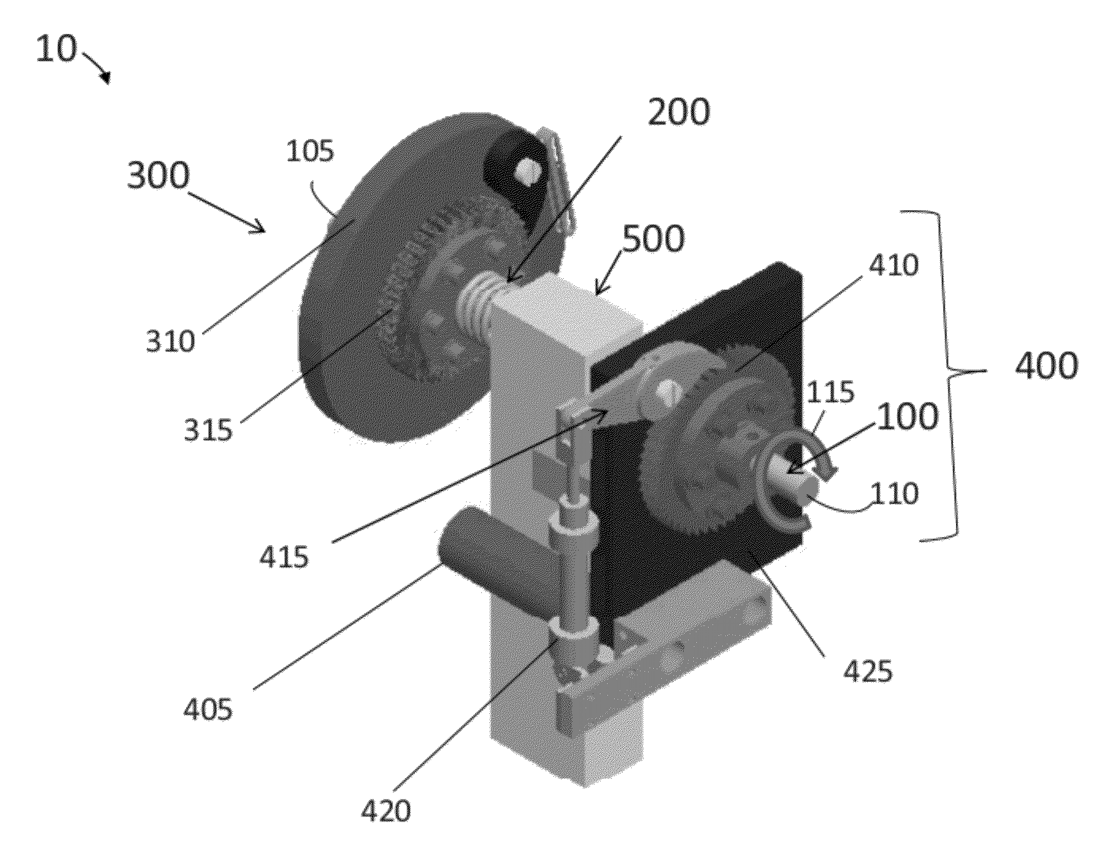
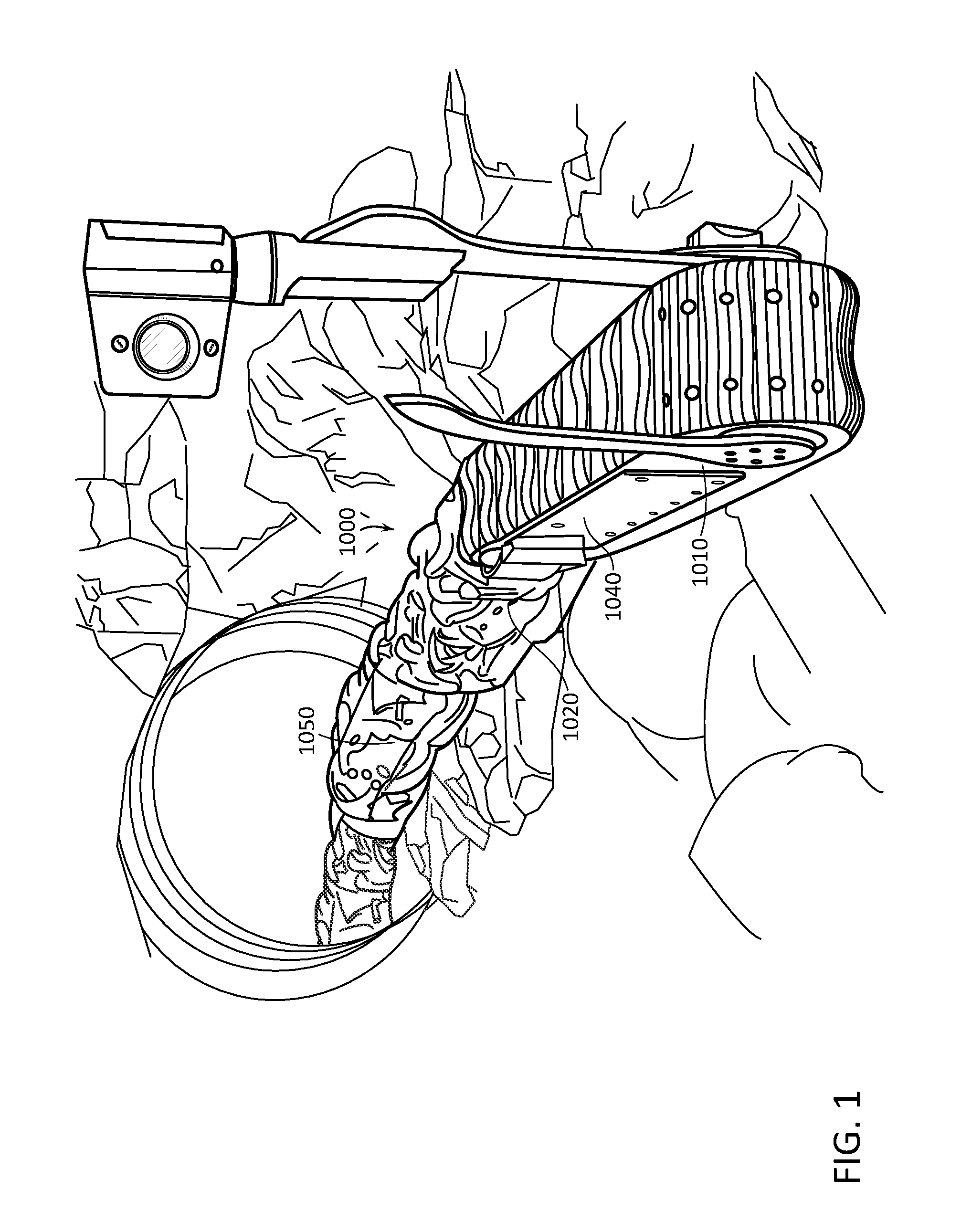
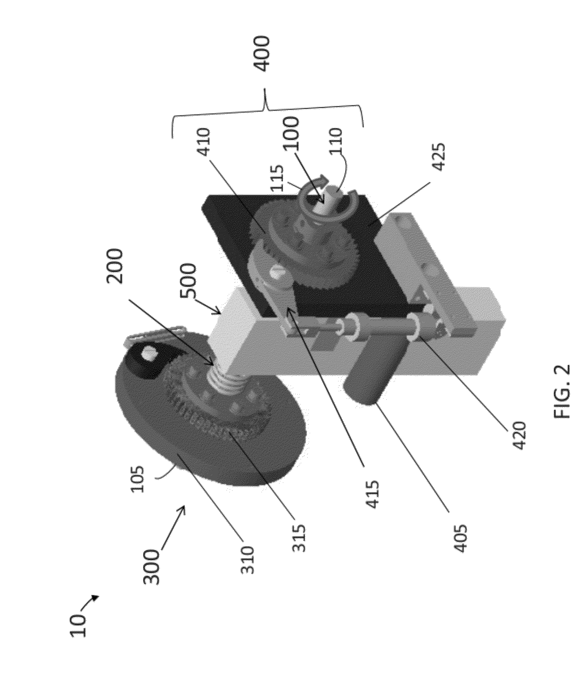
[0024]The energy storage and release technology described herein advantageously simplifies the repeatable and accurately timed storage and release of energy, thereby providing a quick and cost-effective release of energy. The technology can be used, for example, by a machine (e.g., snake robot, wheeled robot with articulated arm, factory machine, human robot, etc.) for the direct application of energy for movement (e.g., jumping, snapping, kicking, biting, hopping, spinning, etc). For example, a robot with a smashing arm utilizes the technology to store energy for the smashing arm and release the stored energy via the smashing arm to hit another item (e.g., a different robot, a door, a window, etc.). As another example, a snake robot with two articulated components utilizes the technology to store energy for the movement of a joint between the two articulated components and release the stored energy via the joint causing the snake robot to jump (e.g., jump over an obstacle, jump up ...


PUM


Abstract

The technology is directed to an energy storage and release system that stores energy and enables a repeatable and accurately timed release of energy. A shaft member supports a drive assembly, a locking assembly and a lever member there between. The lever member and locking assembly are attached to the shaft. The drive assembly rotates freely about the shaft and loads energy into a torsion spring in communication with the lever member. The torsion spring connects at one end to the drive assembly and at the other end to the lever member without contacting the shaft member. The locking assembly provides a triggered release mechanism for selective release of stored energy from the torsion spring that accordingly rotates the lever member. The system can automatically reload the torsion spring once a signal is received from any number of events including, when the rotating lever member contacts a stop member or limit sensor that signals the end of travel for the lever member in either rotational directions.

Description

BACKGROUND[0001]Energy release mechanisms generally require numerous integrated moving parts to selectively engage and disengage a drive train and thereby release stored energy. Such complex systems include, for example, high energy electromagnetic clutches, large mechanical clutches and transmissions, and complex release and escapement mechanisms. These systems are generally complex and prone to multiple modes of failure because of the complexity of enmeshed and / or selectively engaged moving parts. The high part count and associated complexity of manufacture increases overall system cost. Additionally, most of these systems are large and weighty, thereby further hindering their incorporation into agile, articulated robotic devices. A need exists for a device that enables simple transmission, locking, and release of energy.SUMMARY[0002]One approach to energy storage and release is a system. The system includes a shaft member having a proximal end and a distal end. The system further...

Claims


Application Information

Patent Timeline
Patent Type & Authority Applications(United States)
IPC IPC(8): F03G1/00
CPCY10T74/2133F03G1/02
Inventor MCGRAIL, RICHARD A.
Owner RAYTHEON CO
Why Eureka
Try Eureka