
Tin plating solution

a technology of plating solution and plating plate, which is applied in the manufacture of printed circuits, electrical devices, printed circuits, etc., can solve the problems of burn deposits, reducing current density, and complex wiring patterns of printed boards

Inactive Publication Date: 2012-05-31
ROHM & HAAS ELECTRONICS MATERIALS LLC
View PDF5 Cites 10 Cited by
  • Summary
  • Abstract
  • Description
  • Claims
  • Application Information

AI Technical Summary

Benefits of technology

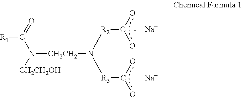
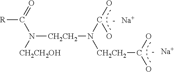
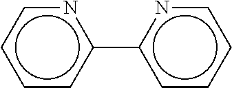
The present invention provides a tin plating solution that has excellent uniformity of plating and film thickness distribution, without any burn deposits. This solution includes a tin ion source, non-ionic surfactants, imidazoline dicarboxylate, and 1,10-phenanthroline. The non-ionic surfactants should have a polyalkylene oxide substituent in the molecule. The solution may also contain antioxidants. This solution can be used for plating printed boards with complex wiring patterns.

Problems solved by technology

However, according to the recent technical development, wiring pattern of printed board becomes more complex, so that the form of goods to be plated also becomes more complex.
Furthermore, lowering the current density reduces burn deposits, but it is not practical because the plating efficiency per time falls.
However, as discussed later, even if non-ionic surfactants are used as the surfactants, the thickness of plating film becomes thin in the section of low current density, so that the film thickness distribution of a plate becomes worse.
However, as discussed later, some compounds with at least two nitrogen atoms described in the patent would still cause the problem of forming a non-uniform plating appearance on a printed board having through-holes.

Method used


Image

  • Tin plating solution
  • Tin plating solution
  • Tin plating solution

Examples


examples

[0023]Evaluation Test

[0024]Hull cell tests and slit hull cell tests were carried out under the following conditions in order to evaluate the performance of plating solution prepared in each examples and comparative examples. In addition, the throwing power was measured in order to evaluate the plating uniformity on through-holes. The hull cell test is a test method for evaluating the plating appearance over a broad range of current densities as well as the film thickness distribution. The slit hull cell test is a test method for evaluating the precipitation properties at low current density.

Conditions

Hull Cell Test

Current: 1 amp

[0025]Plating time: 5 minutes

Stirring speed: 2 m / minute

Bath temperature: 23° C.

Slit Hull Cell Test

Current: 0.1 amp

[0026]Plating time: 3 minutes

Stirring: None

[0027]Bath temperature: 23° C.

Throwing Power

[0028]Bath temperature: 23° C.

Stirring speed: 1.2 m / minute

Plating cell: Haring cell

Amount of solution: 1.5 L

Plating thickness: 7 μm

Current density: 1.5 ASD


PUM

PropertyMeasurementUnit
concentrationaaaaaaaaaa

Abstract

To provide a tin plating solution having uniformity of through-hole plating, uniformity of film thickness distribution and no burn deposits even. The tin plating solution include a tin ion source, at least one non-ionic surfactant, imidazoline dicarboxylate and 1,10-phenanthroline.

Description

FIELD OF THE INVENTION[0001]The present invention relates to a tin plating solution, specifically, a tin plating solution used for a matte tin plating of a metal resist for a printed board.BACKGROUND OF THE INVENTION[0002]Tin plating or tin-lead alloy plating has been used for soldering or etching resists. However, according to the recent technical development, wiring pattern of printed board becomes more complex, so that the form of goods to be plated also becomes more complex. As a result, it is required to form uniform plating films on both fine parts and broad parts at same time. Furthermore, when the printed board to be plated has through-holes, the formation of a uniform plated film even within the through-holes is desired.[0003]Since the conventional tin plating solution which can form a uniform plating film inside through-holes contains a strong suppressor, the precipitated particles becomes bigger, and burn deposits, dendritic precipitation or powder precipitation, readily ...

Claims


Application Information

Patent Timeline
Patent Type & Authority Applications(United States)
IPC IPC(8): C25D3/32C25D5/02
CPCH05K3/062C25D3/32C25D3/30
Inventor HAYASHI, SHINJIROSAKAI, MAKOTOSAITO, MUTSUKO
Owner ROHM & HAAS ELECTRONICS MATERIALS LLC
Learn More