
Liquid anode radiation source

a radiation source and liquid anode technology, applied in the field of xray radiation sources, can solve the problems of uneven anode surface realizable exposure time, melting of anode material in the focal spot, etc., and achieve the effect of cooling or increasing the flowing anode material, reducing the thickness of the liquid anode, and reducing the exposure tim

Active Publication Date: 2012-05-31
GE HUNGARY +1
View PDF5 Cites 8 Cited by
  • Summary
  • Abstract
  • Description
  • Claims
  • Application Information

AI Technical Summary

Benefits of technology

[0015]Beyond this, this disclosure discloses the implementation of a source which can eliminate the above-treated disadvantages of liquid anode radiation sources produced with a separation window. Especially, the purpose is to develop a liquid anode radiation source which has optional orientation, free anode surface from the direction of the arrival of the source beam, which prevents the contamination of the high-voltage accelerating space serving for the production of the source beam with anode material.
[0017]A further advantage of the radiation source(s) of the present disclosure is that efficient anode material condensation can be realized as a result that the anode material flow practically takes place on the whole internal surface of the chambered element forming their body: the returning to liquid phase of the anode material evaporated on the anode focal spot by the source beam is supported by a relatively large condensation surface. In addition, the large condensation surface makes it possible for the heat energy produced during the particle impacts to spread on great amount of the anode material and thereby the heat load and the possibility of the cooling of the radiation source will improve.
[0019]In addition, for certain embodiments of the radiation source(s) of the present disclosure, the flow of the liquid anode material in the radiation source is supported by an electromagnetic pump or Faraday pump arranged advantageously at the outlet serving for the discharge of the anode material from the body surrounding the anode space. Through the application of the Faraday pump, it can be prevented that the anode material flows back into the body (the anode space) through the outlet in certain orientation of the radiation sources (e.g., in their “upside down” position) and accumulating.
[0020]Furthermore, the special geometry of the Faraday pump applied advantageously will also contribute that the flow of the liquid anode material can be stabilized at the outlet.

Problems solved by technology

If the anode is overheated, then it will result in the melting of the anode material in the focal spot and the anode surface in the focal spot will become uneven.
Accordingly, the melting of the anode material at the focal spot will define the shortest realizable exposure time, which is unfavorable for imaging.
It will result in the increase of the external dimensions of the actual diagnostic imaging equipment.
The problem of gallium entering the accelerating space is not solved, so the operability of this liquid anode radiation source is doubtful.
It is a further disadvantage that the flowing back of the liquid anode material into the accelerating space realized in the form of high-voltage vacuum space may easily occur which may result in the failure of the X-ray source.
The considered solutions do not eliminate, only reduce the problem of electron window warming.
As a result, such a relatively thin electron window is subject to fatigue fracture owing to the accumulated thermal and mechanical stress, as it is mentioned by U.S. Pat. No. 7,412,032 and thus, it may lead to the unforeseen failure of the X-ray source.
In addition, the integration of such windows in the X-ray sources will increase the complexity of the manufacturing processes and production costs of liquid anode X-ray sources.

Method used


Image

  • Liquid anode radiation source
  • Liquid anode radiation source
  • Liquid anode radiation source

Examples


Embodiment Construction

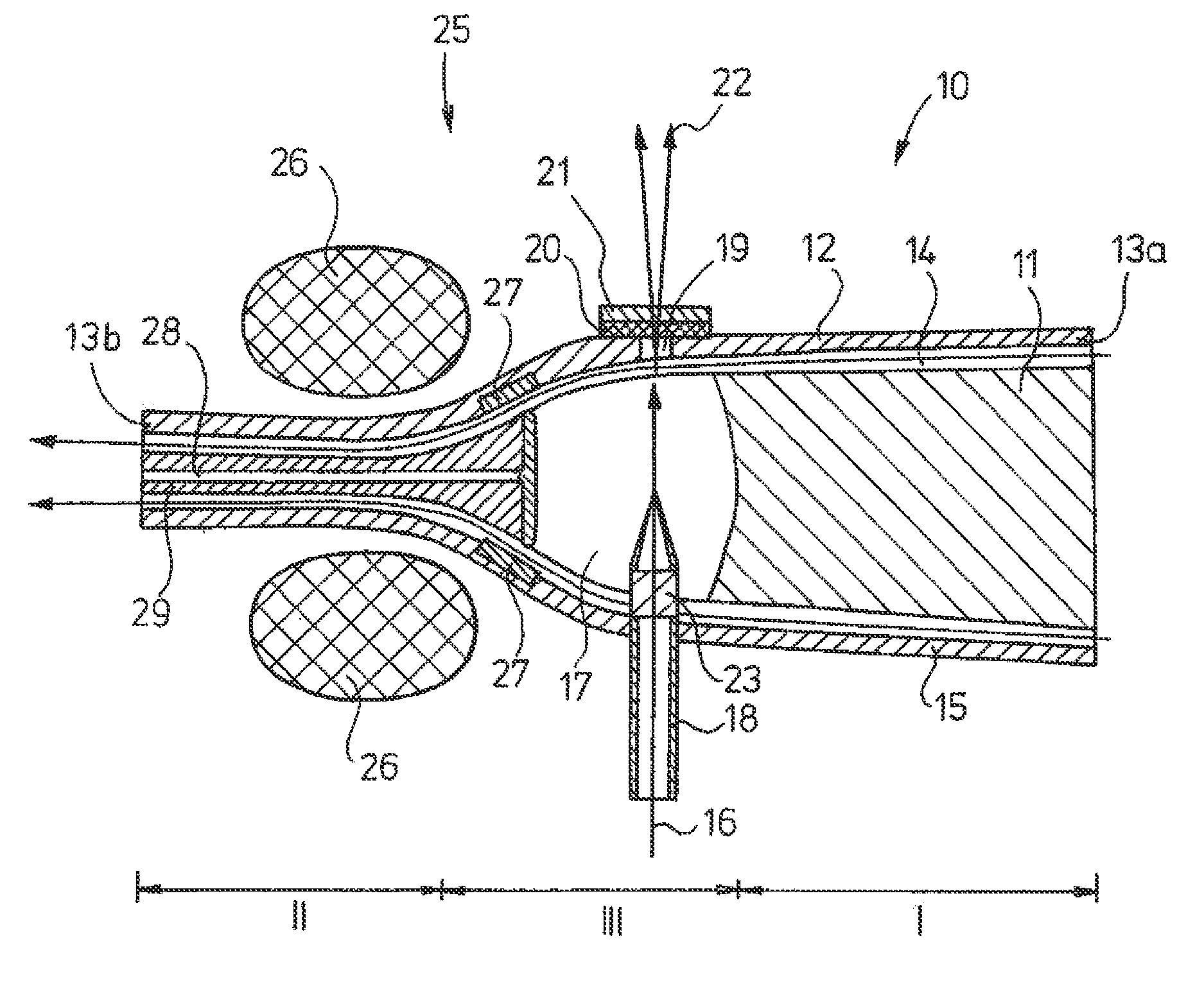
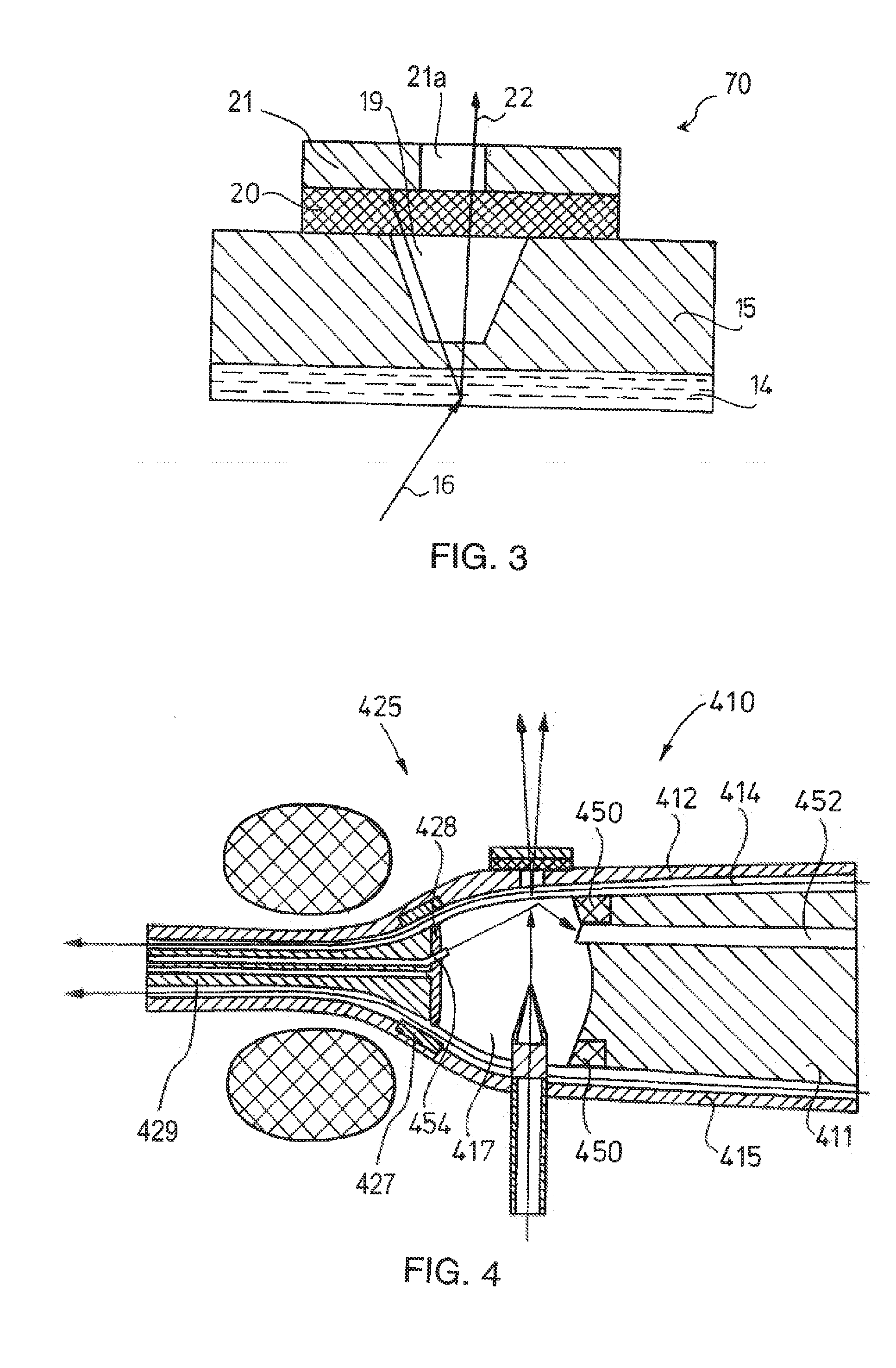
[0033]The similar reference numerals used in the drawings will practically refer to the same unit in each case. In addition, for the sake of simplicity, the flow path of the liquid anode material in the drawings in each case with flow lines running in parallel with the body wall.

[0034]Hereinafter we will describe in more detail the various embodiments of a radiation source of the present disclosure, specifically in connection with various embodiments of a liquid anode X-ray radiation source.

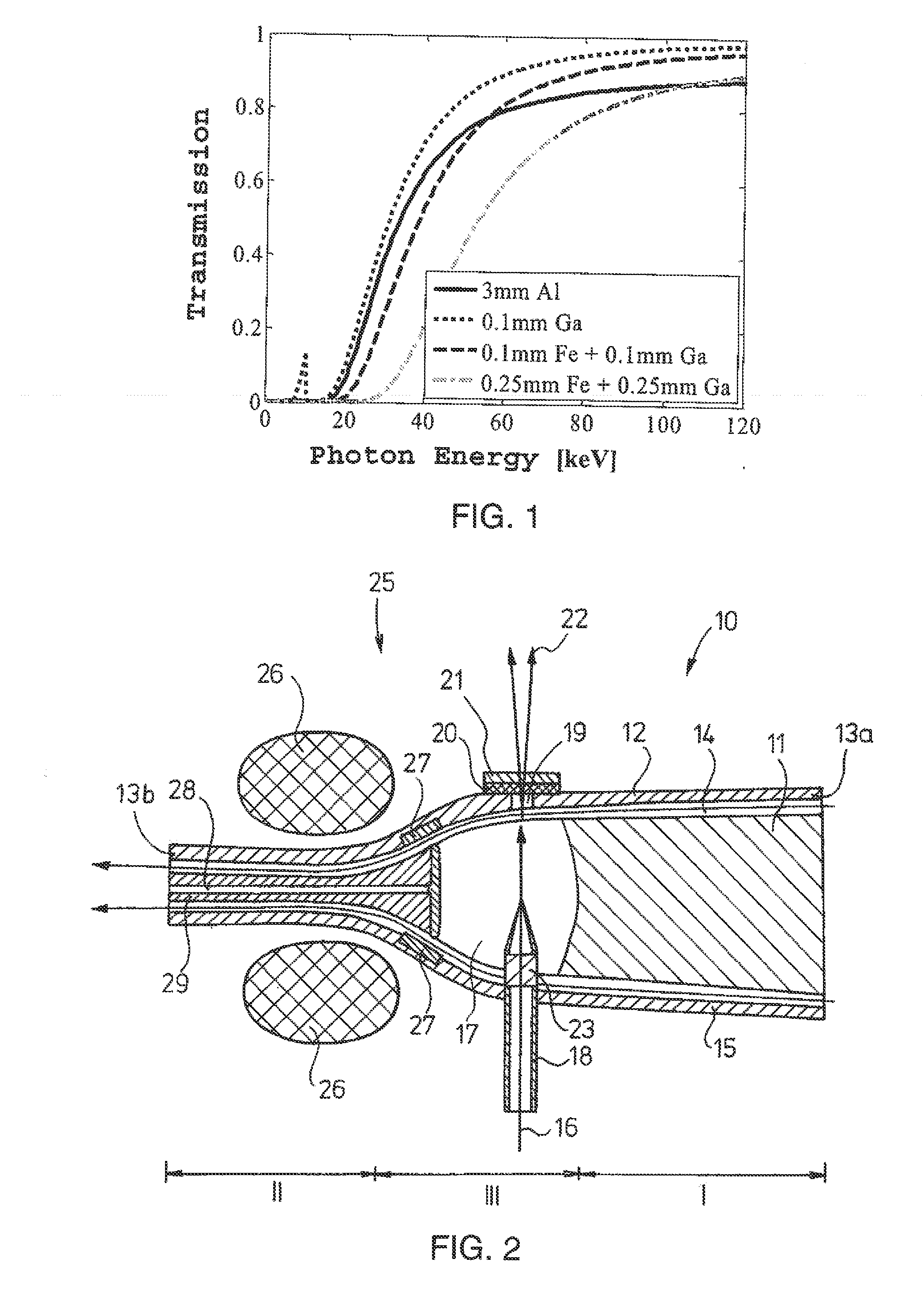
[0035]Referring now to the drawings, FIG. 1 shows transmission of X-ray radiation calculated by the Beer-Lambert principle as a function of the energy of the X-ray radiation that is the photon energy for anode material produced from e.g., liquid gallium (Ga) layered on each other in various thicknesses and solid metal material of specified quality, especially steel (Fe). From FIG. 1, it can be seen that the transmission can be influenced by changing the thickness of the liquid Ga and the solid Fe...


PUM


Abstract

The present disclosure relates to a liquid anode radiation source (10) having the ability of turning upside down. The liquid anode radiation source (10) comprises a body (12) equipped with inlet and outlet having a wall (15) limiting the anode space (17), where the outlet connected to the inlet outside the body (12) will define a continuous flow path closing through the body, the inlet has a wall limiting an internal cross-section changing towards the anode space (17), wherein the cross-section of the inlet a deflector (11) is arranged in a position free of contacting the wall, filling out the cross-section partially and movable to the direction perpendicular to the cross-section; the liquid anode material (14) arranged in the flow path; the circulation unit inserted in the flow path in such a way that it can ensure the unidirectional movement of the anode material in the flow path.

Description

CROSS-REFERENCE TO RELATED APPLICATIONS[0001]This application claims the benefit of a foreign priority patent application filed in Hungary as Application No. P 10 00635, filed on Nov. 26, 2010, and U.S. Provisional Patent Application No. 61 / 417,290, filed on Nov. 26, 2010, both of which are incorporated herein by reference.BACKGROUND OF THE INVENTION[0002]This disclosure relates generally to X-ray radiation sources, and more particularly to a liquid anode radiation source.[0003]The various imaging technologies constitute an accepted and integral part of our everyday life. Applying various types of high-intensity radiation sources (e.g. neutron sources, X-ray sources, etc.) these imaging technologies are widely used in non-destructive quality control (see the neutron diffraction material structure testing methods), security engineering (see airport radioscopic screening) or medical diagnostics.[0004]The imaging technologies based on the use of X-rays constitute a significant group of...

Claims


Application Information

Patent Timeline
IPC IPC(8): H01J13/00
CPCH01J35/08H05H3/06H01J2235/082H01J35/116
Inventor KAKONYI, ROBERT
Owner GE HUNGARY
Learn More