
Optical System Having a Symmetrical Coupling Region

Active Publication Date: 2012-05-31
OCTROLIX
View PDF2 Cites 8 Cited by
  • Summary
  • Abstract
  • Description
  • Claims
  • Application Information

AI Technical Summary

Benefits of technology

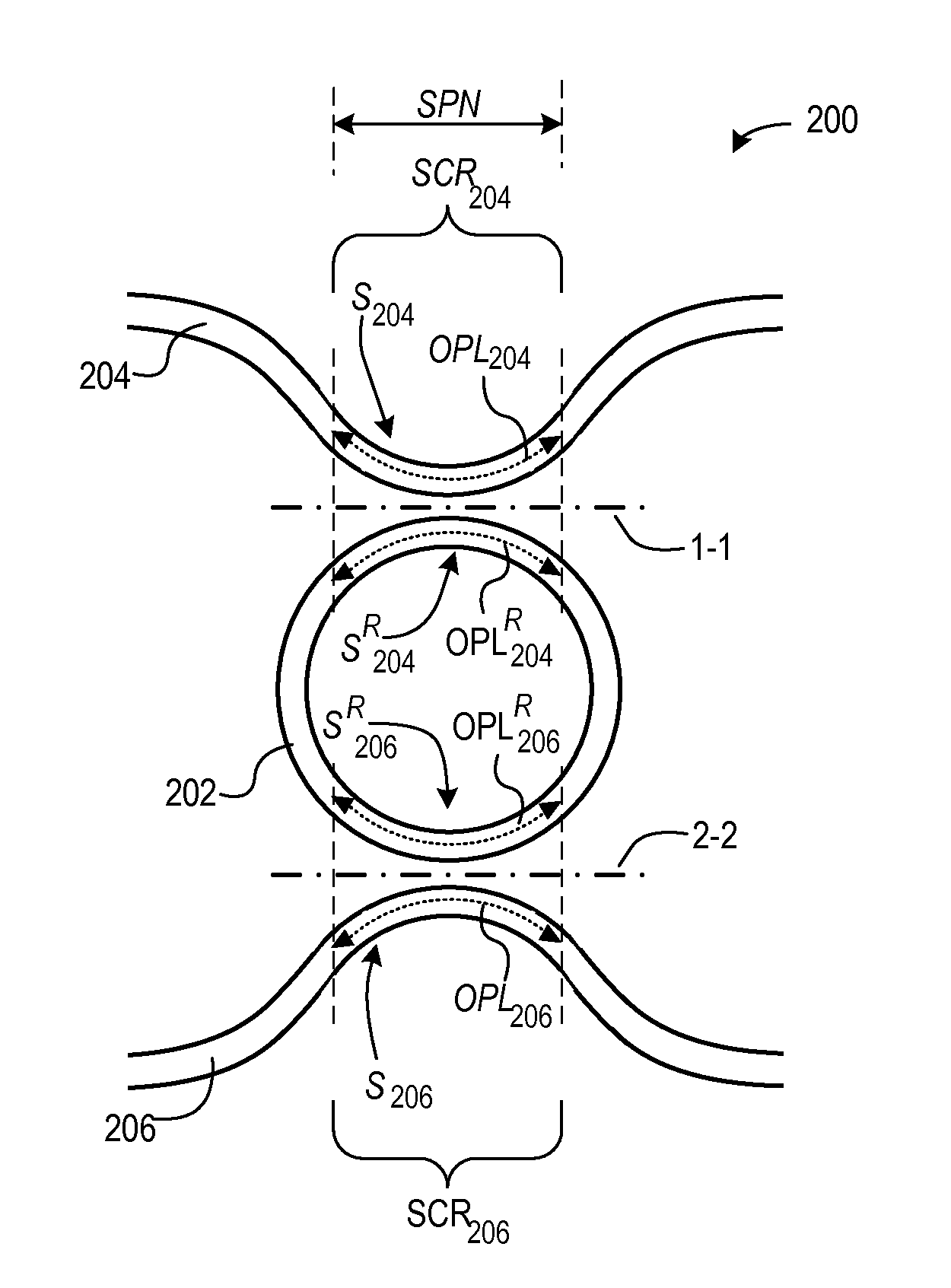
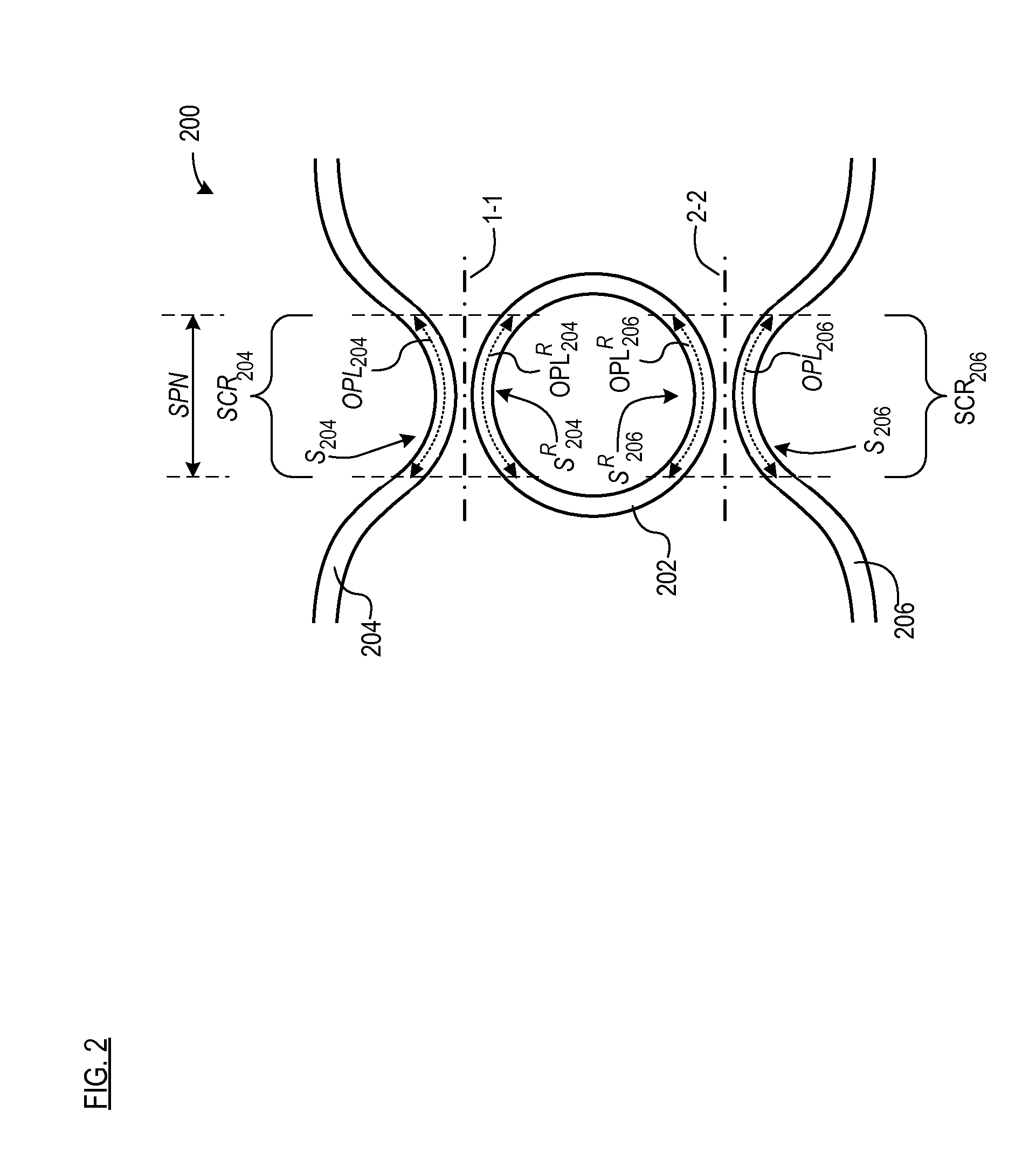
[0020]The present invention provides a new “symmetric” geometry for an optical-coupling region in a system comprising an optically-resonant element. The symmetric optical-coupling region is structured to avoid phase mismatch and also reduce the problem of the wavelength dependence of the coupling factor. Furthermore, the new geometry imposes no limitations on the geometry of the optically-resonant element. Because the coupling factor is less-wavelength dependent, manufacturing tolerances can be relaxed and greater reproducibility can be achieved.

Problems solved by technology

In prior art designs, this has resulted in a trade-off between the required ORTL, minimum bend radius for the loop, and acceptable bend loss.
This leads to the phase mismatch discussed above.
But making such an adjustment necessarily causes an asymmetry of another property (e.g., width, height, etc.) between the bus waveguides and the loop.
Of course, some coupling will occur beyond the straight portions, such that there will be some level of phase mismatch.
In fact, the present inventors found that micro-resonator devices they produced for operation at 850 nanometers operation were not functioning properly.

Method used


Image

  • Optical System Having a Symmetrical Coupling Region
  • Optical System Having a Symmetrical Coupling Region
  • Optical System Having a Symmetrical Coupling Region

Examples


Embodiment Construction

[0034]FIG. 2 depicts integrated micro-resonator 200 having symmetric coupling regions in accordance with the illustrative embodiment of the present invention. The integrated micro-resonator includes loop waveguide 202, bus waveguide 204, and bus waveguide 206.

[0035]It is desirable for loop waveguide 202 to be very small so that: (i) its free spectral range is large and (ii) it occupies very little physical space, thereby enabling large-scale integration. In fact, a typical loop waveguide for an integrated micro-resonator has a diameter that is only one or two orders of magnitude greater than its operating wavelength. So, for a datacom application having an operating wavelength of about 850 nanometers, loop diameter is usually in the range of about 10 microns to about 100 microns.

[0036]To guide light around the tight radius of curvature of loop waveguide 202, the dielectric contrast (i.e., difference in refractive indices) between the loop waveguide and surrounding medium in the plan...


PUM


Abstract

A system having an optical-coupling region for evanescently coupling light between first and second optical-waveguiding structures is disclosed. Within the optical-coupling region, the first and second optical-waveguiding structures exhibit mirror symmetry with respect to each other across or about at least one of a plane and an axis and include a segment that is not straight.

Description

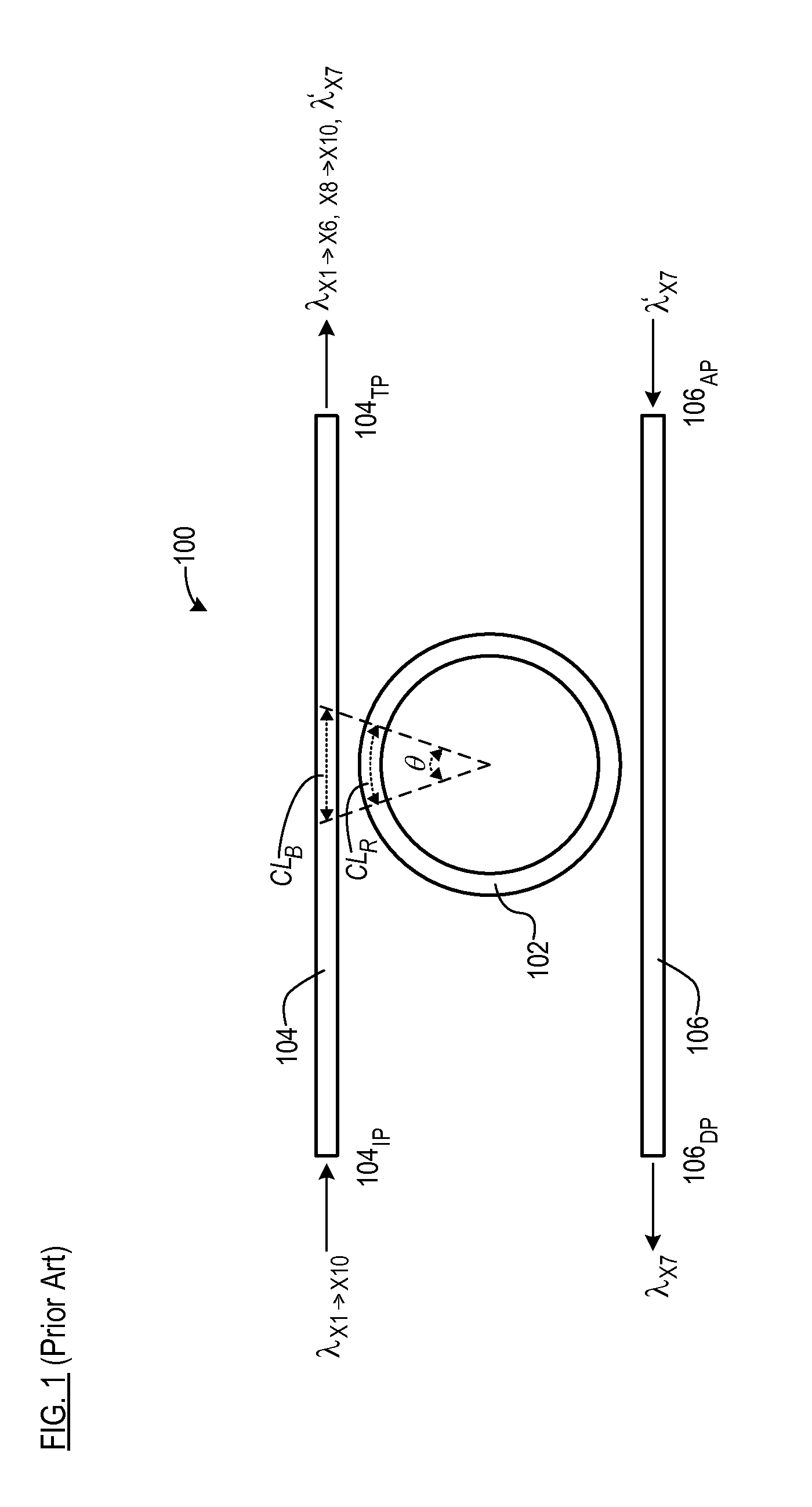
FIELD OF THE INVENTION[0001]The present invention relates to coupled waveguiding elements.BACKGROUND OF THE INVENTION[0002]A micro-resonator is a single, uninterrupted, integrated optical waveguide element in the form of a closed loop that supports at least one resonant mode. The resonance wavelength(s) of the resonator is (are) a function of its optical length (i.e., path length and refractive index). The loop can be circular, “race track” (i.e., oval), elliptical, or even have an arbitrarily curved circumference.[0003]The micro-resonator, which is often called a “ring resonator,” is typically used in conjunction with one or more linear waveguide regions. For example, FIG. 1 depicts a conventional four-port micro-resonator system (integrated micro-resonator”) 100 including loop waveguide 102 and two linear or “bus” waveguides 104 and 106. Bus waveguide 104 includes input port 104IP and through port 104TP. Bus waveguide 106 includes drop port 106DP and add port 106AP. A portion of e...

Claims


Application Information

Patent Timeline
IPC IPC(8): G02B6/26
CPCG02B6/12007G02B6/125G02B2006/121G02B2006/12097G02B6/29338
Inventor HOEKMAN, MARCELHEIDEMAN, RENE GERRITPRAK, ALBERT
Owner OCTROLIX
Learn More