Superconducting direct current transmission system

a direct current transmission and superconducting technology, applied in the direction of superconducting magnets/coils, magnetic bodies, connection contact material, etc., can solve the problems of limiting the ability of energy providers, failure of any one system, and numerous limitations and drawbacks of existing technology, so as to reduce the enormous i2r power loss and adequate chilling

Inactive Publication Date: 2012-06-07
LIGHTHOUSE ENERGY SOLUTIONS
View PDF6 Cites 12 Cited by
  • Summary
  • Abstract
  • Description
  • Claims
  • Application Information

AI Technical Summary

Benefits of technology

[0008]The express purpose in constructing the system utilizing superconducting metal is to extensively reduce the enormous I2R power losses, which would normally occur in a 50 kA conductor. The superconducting material must be chilled at a low temperature to gain superconducting characteristics. The cooling capabilities of various elements at their melting temperatures can provide adequate chilling. Examples of elements, which can be considered, include (but are not limited to) helium (3.2° K), hydrogen (14.2° K), and neon (24.2° K).
[0011]One approach to providing an energy transport means is to utilize the disclosed inventive system described herein which will provide for extending the length of a transmission segment up to 1,000 kilometers. This can be done in combination with the utilization of superconductivity to eliminate most of the energy loss existing in AC and DC systems presently in operation. The disclosed coaxial transmission line can be protected by three-phase AC circuit breakers the details of which will be described.
[0015]It is the objective of this invention to assemble the transmission line components into transmission segments, which can be connected together to extend the transmission line length to make possible the delivery of both electrical and hydrogen energy to appropriate distribution locations across great distances.

Problems solved by technology

The failure of any one system cannot be supported by another, and the fact that these networks fail to communicate and interface limits the ability of energy providers to support peak demands and take advantage of regional capabilities and time zones.
The existing technology has numerous limitations and drawbacks.
One drawback is that line losses equivalent to I2R heating amounts to 6.2% to 7.0% of the energy carried by the transmission line.
These transpositions result in increased construction costs.
Another drawback is the inability to communicate, support, and coexist in multiple markets.
This inability to support distant needs ultimately results in a cascade effect by contributing to uncontrollable pricing fluctuations.
Yet another drawback is that transmission line inductance can and does result in generating a current component, which lags behind the voltage.
This component will increase I2R losses and can contribute to system stability problems.
This requires expensive and complex solutions to reduce the lagging component magnitude.

Method used


Image

  • Superconducting direct current transmission system
  • Superconducting direct current transmission system
  • Superconducting direct current transmission system

Examples


Embodiment Construction

DC Superconducting Transmission Line Segment Protected by Three Phase AC Circuit Breakers

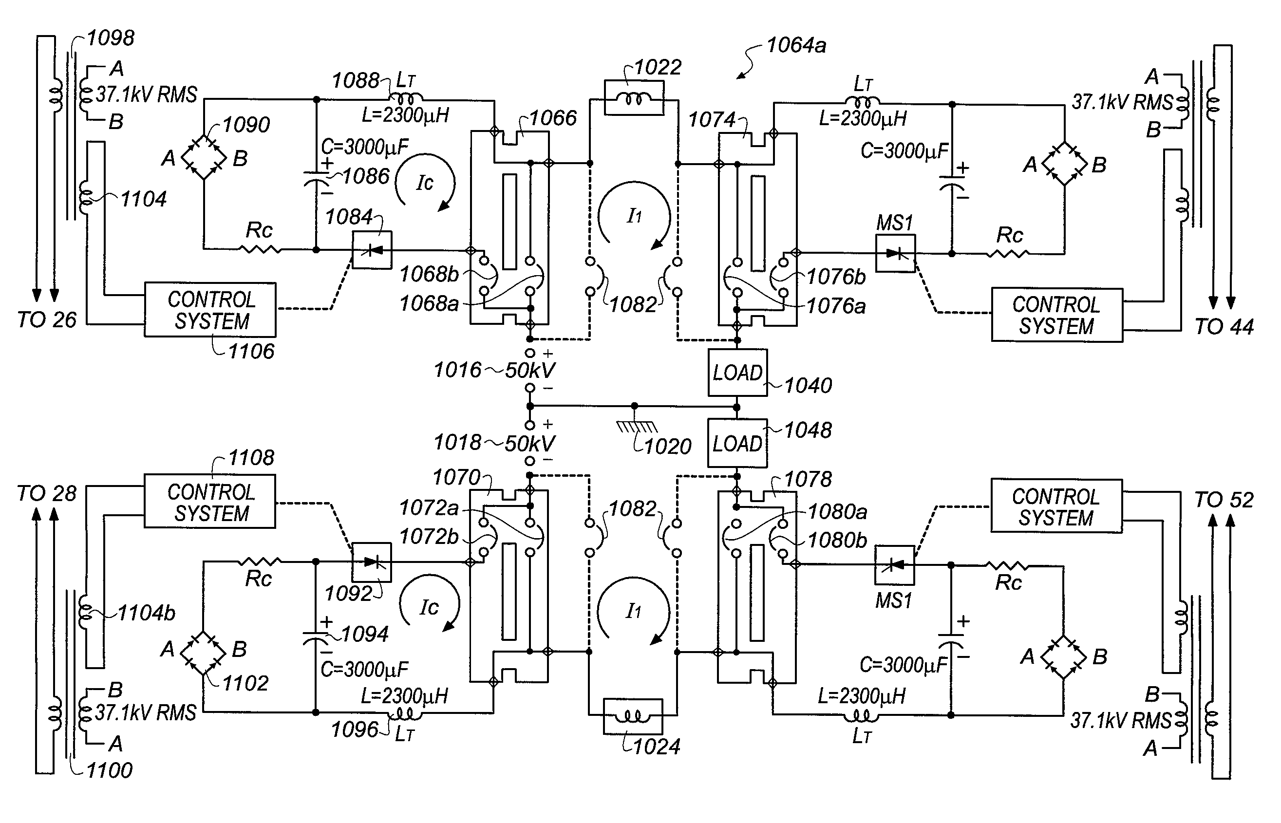
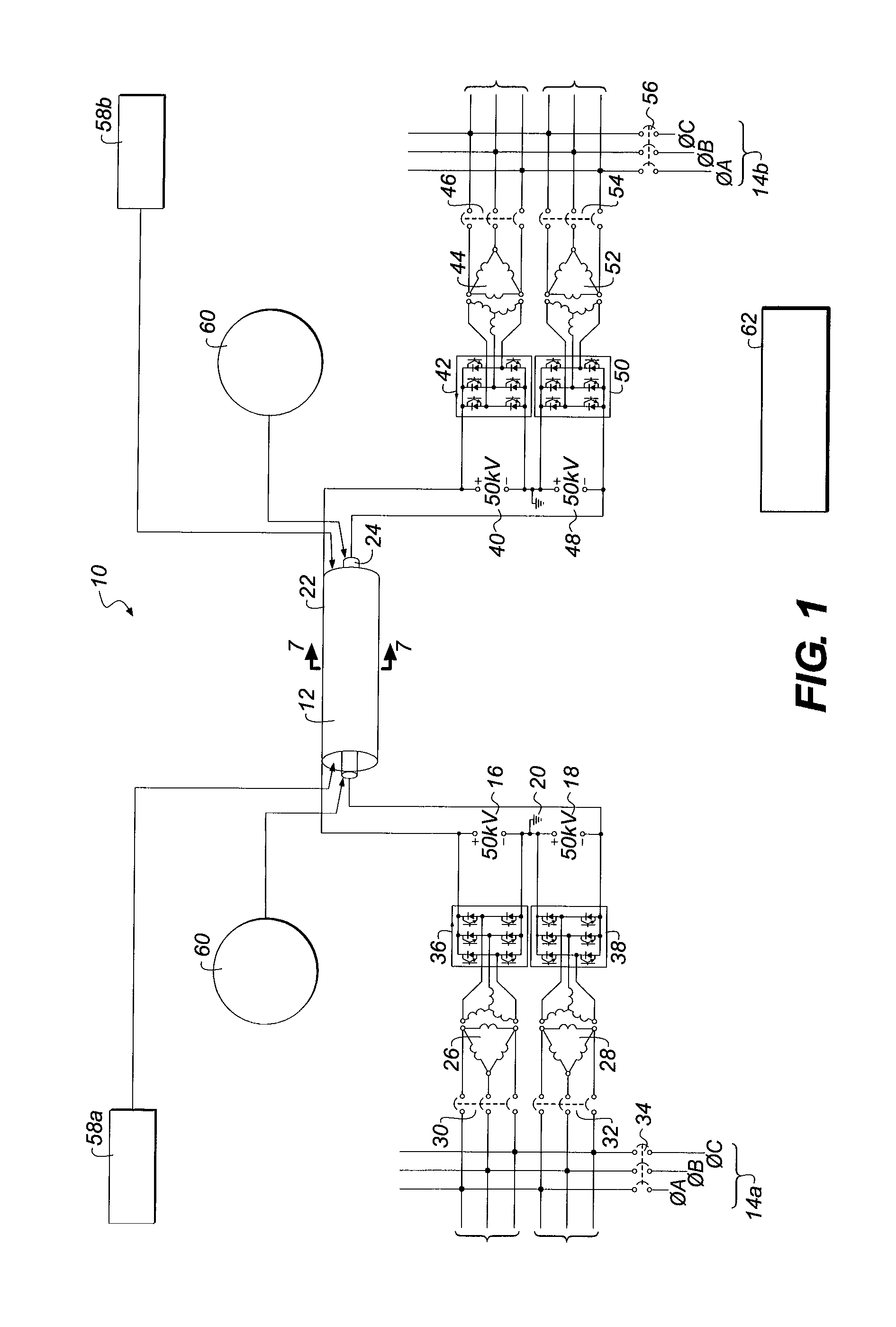
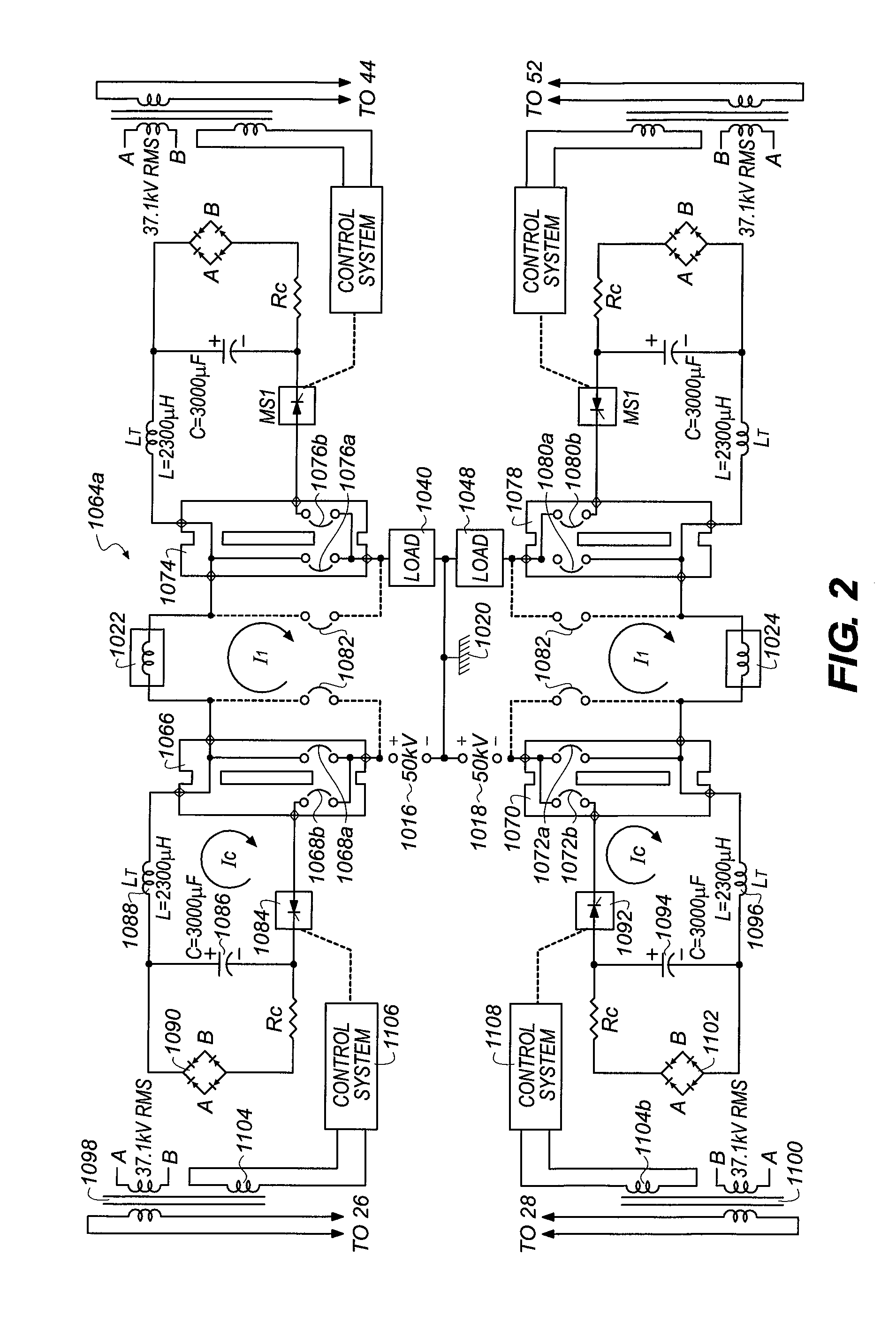
[0035]The proposed objective is to provide a new and unique way of transporting 50 kA DC at a voltage of 100 kV DC while minimizing or eliminating I2R losses through the use of superconductivity. The creation of a transmission segment which combines three-phase AC circuit breakers for protection and isolation with a coaxial superconducting transmission line meets the objective. The disclosed embodiment describes the 50 kA, 100 kV requirements, though choosing higher voltage and reduced current levels are contemplated within the scope of the invention.

[0036]Referring to FIG. 1, a direct current superconducting transmission system 10 includes a 5,000 megawatt coaxial transmission segment 12 coupled between terminals of a local electrical grid or network 14a. The superconducting transmission system 10 includes a 50 kV positive voltage source 16 and a 50 kV negative voltage source 18, which share a...


PUM

PropertyMeasurementUnit
DC voltageaaaaaaaaaa
lengthaaaaaaaaaa
voltageaaaaaaaaaa

Abstract

A DC superconducting coaxial transmission system provides electrical transmission of 5,000 megawatts of energy while simultaneously delivering liquid hydrogen. The transmission system includes a coaxial transmission segment including an inner superconductor, an outer superconductor disposed in surrounding relation to the inner conductor, and a dielectric insulator disposed between the inner superconductor and the outer superconductor. Liquid hydrogen surrounds the superconductors. Three phase transformers and poly phase rectifier / inverters provide a DC voltage source to the superconductors from the electrical grid. In one embodiment, a switching circuit connected between the voltage source and the superconductor injects a cancellation current component into the direct current flow. The cancellation current component is polarized to flow in a direction opposite to the direct current flow to produce a current zero, thus enabling safe interruption of the high DC current while minimizing the magnitude of transient voltages during switching.

Description

CROSS REFERENCE TO RELATED APPLICATION [0001]Reference is made to and this application claims priority from and the benefit of U.S. Provisional Application Ser. No. 61 / 418,946, filed 2 Dec. 2010, entitled “An Electrical and Hydrogen Transmission System Consisting of Specially Designed Segments”, and U.S. Provisional Application Ser. No. 61 / 522,456, filed 11 Aug. 2011, entitled “Transmission System for Electricity and Hydrogen Including Specially Designed Segments”, which applications are incorporated herein in its entirety by reference.FIELD OF THE INVENTION [0002]This invention relates to the field of DC power transmission as a viable means of energy transport over long distances and more specifically, addresses switching and control systems designed to safely deliver energy through the use of superconductor technology.BACKGROUND OF THE INVENTION[0003]Currently, power transmission in the United States relies on an alternating current (AC) transmission network with three distinctly ...

Claims


Application Information

Patent Timeline
Patent Type & Authority Applications(United States)
IPC IPC(8): H01P1/00H01B12/02H02J3/36
CPCH02G15/34H02J2003/365Y02E40/648H01B12/16H02J3/36H01B12/02Y02E60/60Y02E40/60
Inventor CARTER, WILLIAM A.CARTER, SCOTT C.PYLKKANEN, ILKKA T.
Owner LIGHTHOUSE ENERGY SOLUTIONS
Why Eureka
Try Eureka