Combustion control apparatus of internal combustion engine

a combustion control and internal combustion engine technology, applied in the direction of electrical control, process and machine control, instruments, etc., can solve the problems of worsening of exhaust emissions, achieve the effect of suppressing the amount of nox produced, increasing the proportion of premixed combustion, and promoting ignition delay

Active Publication Date: 2012-06-07
TOYOTA JIDOSHA KK
View PDF18 Cites 29 Cited by
  • Summary
  • Abstract
  • Description
  • Claims
  • Application Information

AI Technical Summary

Benefits of technology

[0035]According to the present invention, executing fuel injection in a continuous manner for a period from before compression top dead center of a piston to after compression top dead center promotes a cooling effect in the fuel spray injected in that pe...

Problems solved by technology

On the other hand, if the air-fuel mixture undergoes incomplete combustion during combustion in the...

Method used


Image

  • Combustion control apparatus of internal combustion engine
  • Combustion control apparatus of internal combustion engine
  • Combustion control apparatus of internal combustion engine

Examples


Embodiment Construction

[0047]An embodiment of the invention is described below with reference to the drawings. In this embodiment, a case will be described in which the present invention is applied to a common rail in-cylinder direct injection multi-cylinder (for example, inline four-cylinder) diesel engine (compression self-ignition internal combustion engine) mounted in an automobile.

[0048]—Engine Configuration—

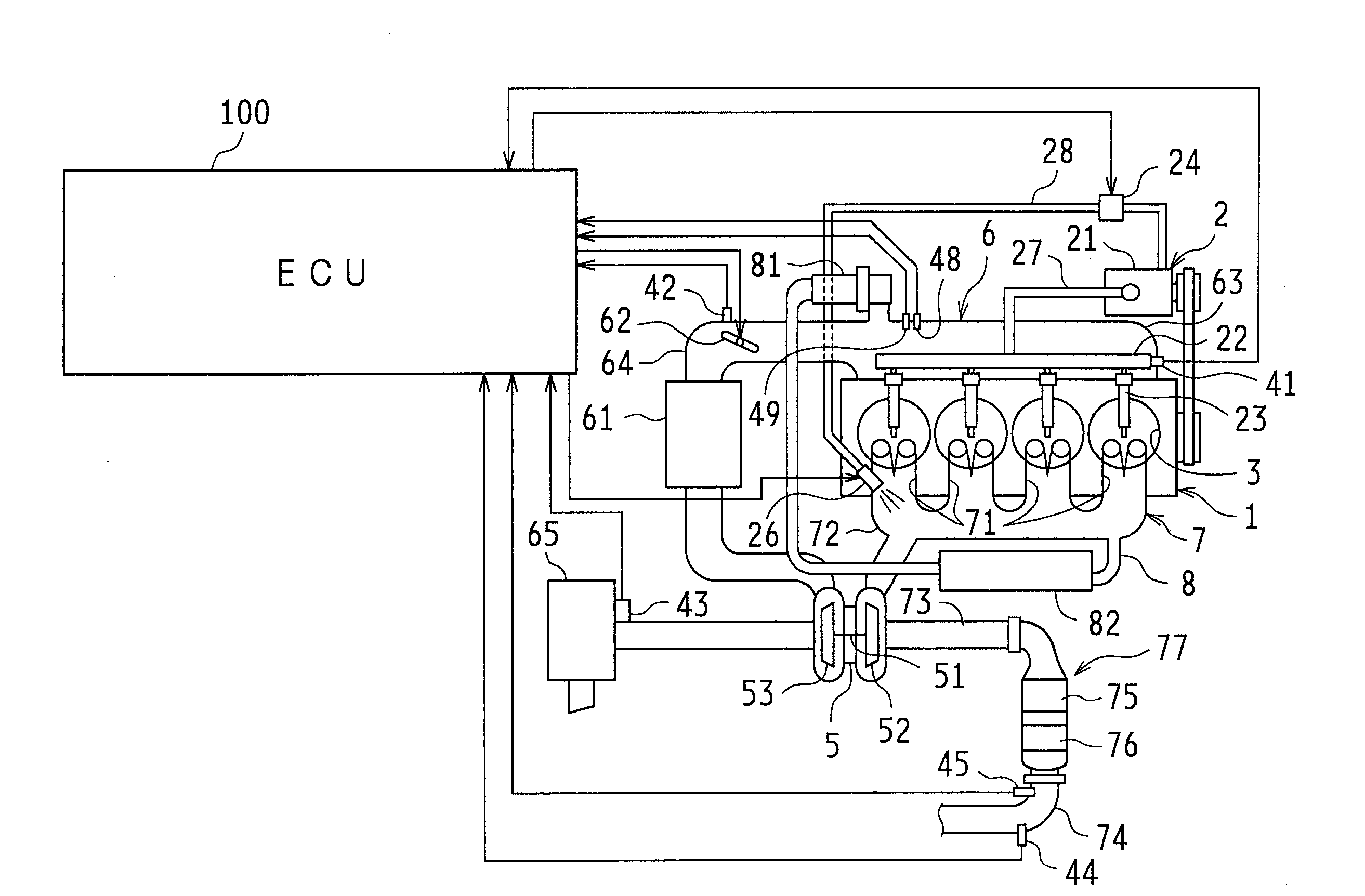
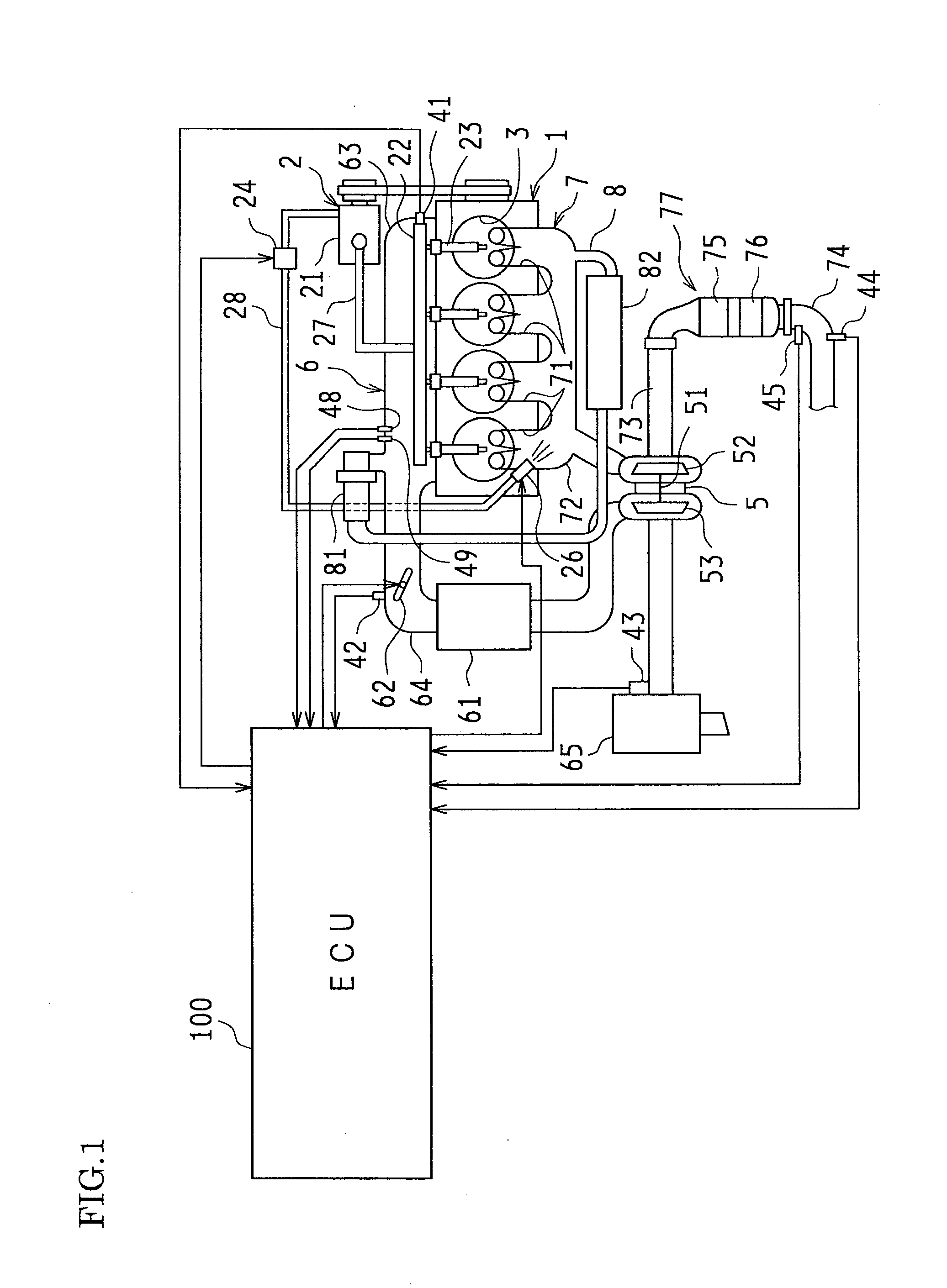
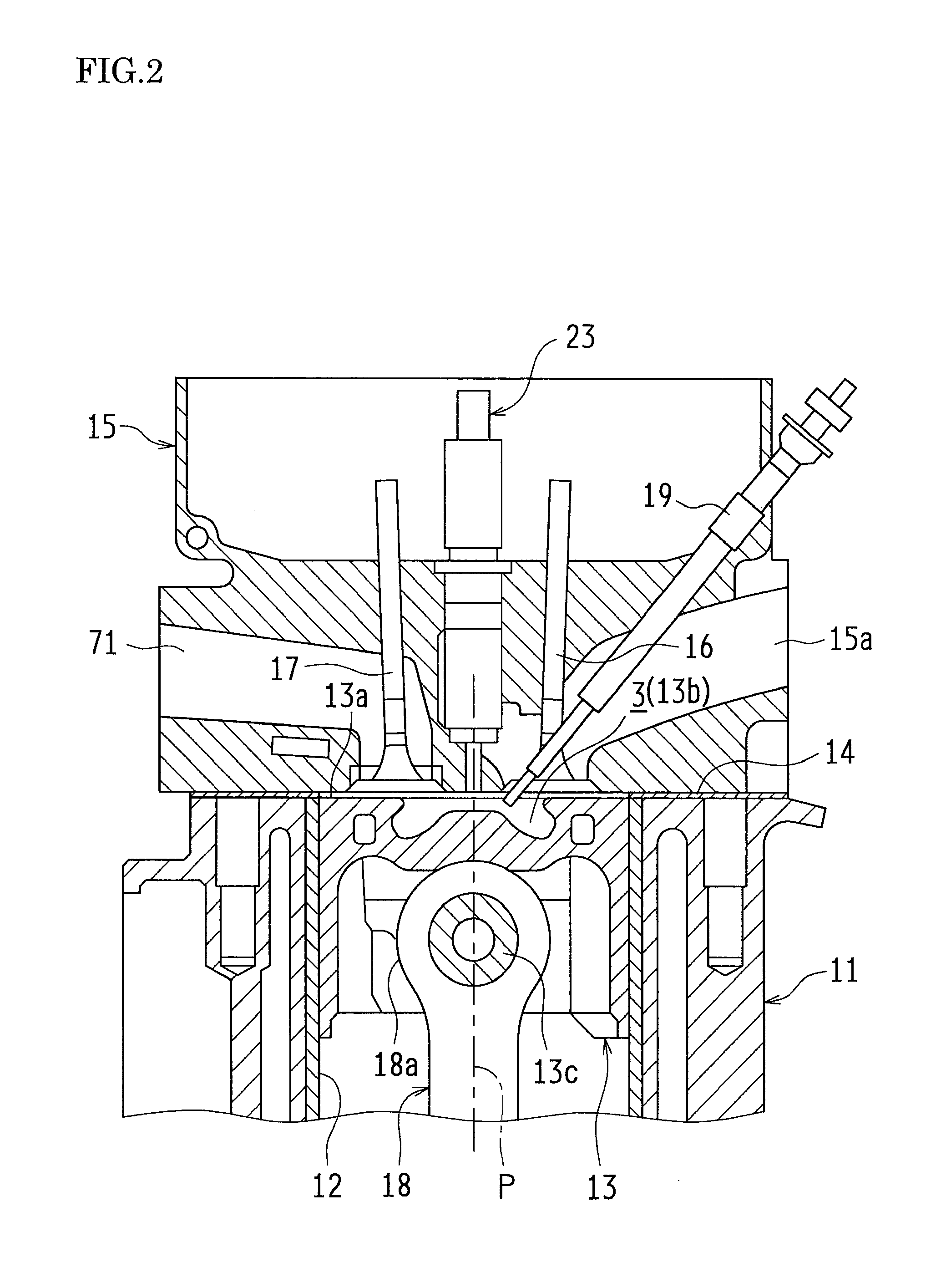
[0049]First, the overall configuration of a diesel engine (referred to below as simply the engine) according to the present embodiment will be described. FIG. 1 is a schematic configuration diagram of an engine 1 and a control system of the engine 1 according to the present embodiment. Also, FIG. 2 is a cross-sectional diagram showing a combustion chamber 3 of the diesel engine and its surroundings.

[0050]As shown in FIG. 1, the engine 1 according to the present embodiment is configured as a diesel engine system having a fuel supply system 2, combustion chambers 3, an intake system 6, an exhaust s...


PUM


Abstract

During high-load operation of an engine, fuel for initial slow-burning combustion and premixed combustion is injected into a combustion chamber by continuous fuel injection, then fuel injection is paused, and fuel for diffusion combustion is injected after a predetermined interval has elapsed. Also, the fuel injection amount in the continuous fuel injection is set higher than the fuel injection amount for diffusion combustion. A spray autointerference cooling effect is achieved by the continuous fuel injection, thus promoting ignition delay so as to increase the proportion of premixed combustion, thereby suppressing the production of smoke. This enables high-volume EGR to be performed, thus enabling reducing the amount of NOx produced.

Description

[0001]This is a 371 national phase application of PCT / JP2009 / 068131 filed 21 Oct. 2009, the content of which is incorporated herein by reference.FIELD OF THE INVENTION[0002]The present invention relates to a combustion control apparatus of a compression self-ignition internal combustion engine represented by a diesel engine. In particular, the present invention relates to a countermeasure for improving exhaust emissions.BACKGROUND OF THE INVENTION[0003]In engines that perform lean combustion, such as diesel engines, an operation range in which an air-fuel mixture having a high air-fuel ratio (lean atmosphere) is caused to combust accounts for most of the entire operation range, thus causing concern regarding the emission of a relatively large amount of nitrogen oxides (hereinafter referred to as NOx). As a countermeasure, it is known to provide an EGR (Exhaust Gas Recirculation) apparatus that recirculates part of the exhaust gas into the intake path (e.g., see PTL 1 and PTL 2). Spe...

Claims


Application Information

Patent Timeline
IPC IPC(8): F02D41/30F02D41/26
CPCF02D41/1446F02D41/3029F02D41/3035F02D41/3809Y02T10/47F02D35/025F02D41/005Y02T10/44F02D41/402Y02T10/40
Inventor NADA, MITSUHIRO
Owner TOYOTA JIDOSHA KK
Why Eureka
Try Eureka