
Bottom up fill in high aspect ratio trenches

a high aspect ratio, bottom-up filling technology, applied in the direction of liquid surface applicators, chemical vapor deposition coatings, coatings, etc., can solve the problems of increasing the difficulty of void-free filling of narrow width, increasing the difficulty of high aspect ratio (ar) features, and reducing the number of voids, so as to improve the subsequent bottom-up filling of the gap, reduce the delay of nucleation, and reduce the difficulty of nucleation

Inactive Publication Date: 2012-06-14
NOVELLUS SYSTEMS
View PDF14 Cites 408 Cited by
  • Summary
  • Abstract
  • Description
  • Claims
  • Application Information

AI Technical Summary

Benefits of technology

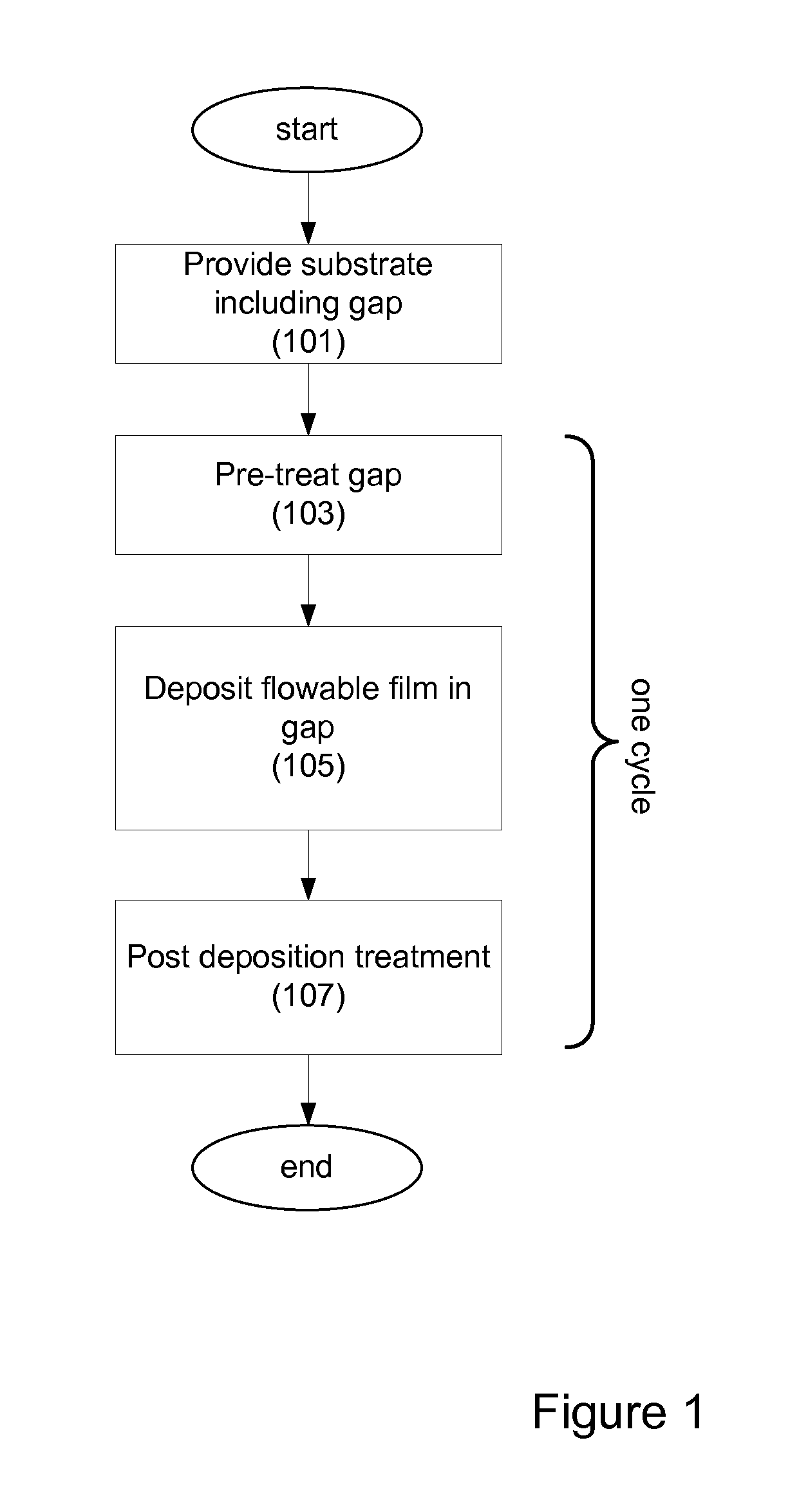
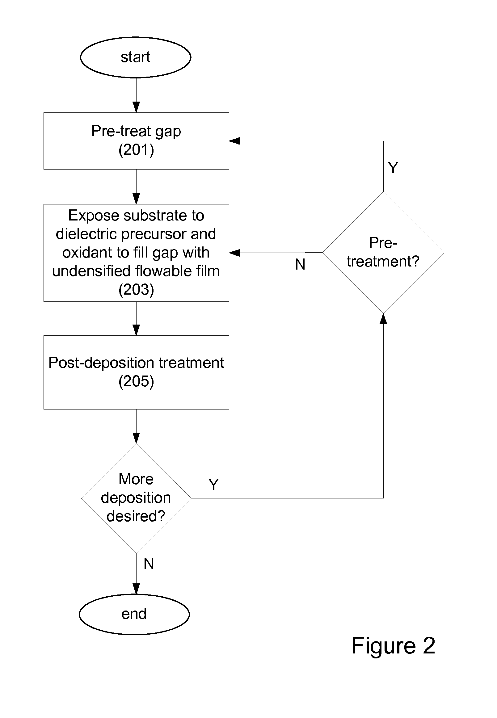
[0003]Provided are novel methods of filling gaps with a flowable dielectric material. According to various embodiments, the methods involve performing a surface treatment on the gap to enhance subsequent bottom up fill of the gap. In certain embodiments, the treatment involves exposing the surface to activated species, such as activated species of one or more of nitrogen, oxygen, and hydrogen. In certain embodiments, the treatment involves exposing the surface to a plasma generated from a mixture of nitrogen and oxygen. The treatment may enable uniform nucleation of the flowable dielectric film, reduce nucleation delay, increase deposition rate and enhance feature-to-feature fill height uniformity. Also provided are apparatuses for implementing the methods described herein.

Problems solved by technology

As device geometries shrink and thermal budgets are reduced, void-free filling of narrow width, high aspect ratio (AR) features (e.g., AR>6:1) becomes increasingly difficult due to limitations of existing deposition processes.
Such a process may involve biasing the substrate.
For example, in certain embodiments, the post-deposition operation may create a top densified portion or crust on which nucleation is difficult.
For example, in some cases H2 pre-treatment prior to deposition of carbon-doped films provides good bottom up gap fill, while N2 / O2 pre-treatment may result in incomplete coverage.
They may also increase the miscibility of the dielectric precursor with the other reactants, especially when condensed in the liquid phase.
High temperature and low pressure will result in slower deposition time.
Thus, increasing temperature may require increased pressure.
This may result in a top-down conversion of the flowable film to a densified solid film.

Method used


Image

  • Bottom up fill in high aspect ratio trenches
  • Bottom up fill in high aspect ratio trenches
  • Bottom up fill in high aspect ratio trenches

Examples


Embodiment Construction

[0030]INTRODUCTION

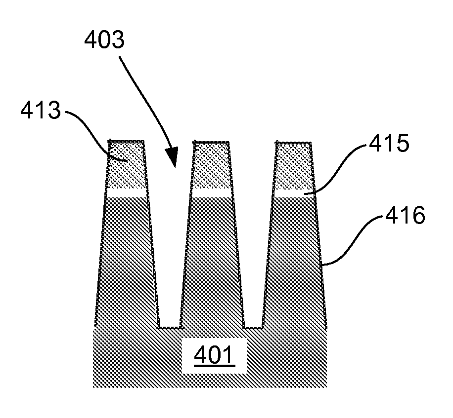
[0031]The present invention pertains to methods of filling gaps on a substrate. In certain embodiments, the methods pertain to filling high aspect (AR) ratio (typically at least 6:1, for example 7:1 or higher), narrow width (e.g., sub-50 nm) gaps. In certain embodiments, the methods pertain filling both low AR gaps (e.g., wide trenches). Also in certain embodiments, gaps of varying AR may be on the substrate, with the embodiments directed at filling low and high AR gaps.

[0032]It is often necessary in semiconductor processing to fill high aspect ratio gaps with insulating material. This is the case for shallow trench isolation (STI), inter-metal dielectric (IMD) layers, inter-layer dielectric (ILD) layers, pre-metal dielectric (PMD) layers, passivation layers, etc. As device geometries shrink and thermal budgets are reduced, void-free filling of narrow width, high aspect ratio (AR) features (e.g., AR>6:1) becomes increasingly difficult due to limitations of existing...


PUM

PropertyMeasurementUnit
Dielectric polarization enthalpyaaaaaaaaaa
Flow rateaaaaaaaaaa
Ratioaaaaaaaaaa

Abstract

Provided are novel methods of filling gaps with a flowable dielectric material. According to various embodiments, the methods involve performing a surface treatment on the gap to enhance subsequent bottom up fill of the gap. In certain embodiments, the treatment involves exposing the surface to activated species, such as activated species of one or more of nitrogen, oxygen, and hydrogen. In certain embodiments, the treatment involves exposing the surface to a plasma generated from a mixture of nitrogen and oxygen. The treatment may enable uniform nucleation of the flowable dielectric film, reduce nucleation delay, increase deposition rate and enhance feature-to-feature fill height uniformity.

Description

CROSS-REFERENCE TO RELATED APPLICATION[0001]This application claims priority under 35 U.S.C. §119(e) to U.S. Provisional Application 61 / 421,562 entitled “BOTTOM UP FILL IN HIGH ASPECT RATIO TRENCHES,” filed Dec. 9,2010, all of which is incorporated in its entirety by this reference.BACKGROUND OF THE INVENTION[0002]It is often necessary in semiconductor processing to fill high aspect ratio gaps with insulating material. This is the case for shallow trench isolation (STI), inter-metal dielectric (IMD) layers, inter-layer dielectric (ILD) layers, pre-metal dielectric (PMD) layers, passivation layers, etc. As device geometries shrink and thermal budgets are reduced, void-free filling of narrow width, high aspect ratio (AR) features (e.g., AR>6:1) becomes increasingly difficult due to limitations of existing deposition processes.SUMMARY OF THE INVENTION[0003]Provided are novel methods of filling gaps with a flowable dielectric material. According to various embodiments, the methods in...

Claims


Application Information

Patent Timeline
IPC IPC(8): H01L21/31C23C16/02C23C16/40
CPCC23C16/02C23C16/045C23C16/401H01L21/02211H01L21/02216H01L21/76224H01L21/02274H01L21/02315H01L21/02318H01L21/67207H01L21/02219
Inventor NITTALA, LAKSHMINARAYANASHANNON, KARENADRAEGER, NERISSARATHOD, MEGHATE NIJENHUIS, HARALDVAN SCHRAVENDIJK, BARTDANEK, MICHAEL
Owner NOVELLUS SYSTEMS
Learn More