Engine control unit

Active Publication Date: 2012-06-21
HONDA MOTOR CO LTD
View PDF5 Cites 4 Cited by
  • Summary
  • Abstract
  • Description
  • Claims
  • Application Information

AI Technical Summary

Benefits of technology

[0014]According to the first to sixth features, when an increment in crank angular velocity is calculated at two points in one cycle so as to calculate a crank angular velocity variation, a reluctor used for detecting the crank angular velocity at one point (near the compression top d

Problems solved by technology

However, there has been a problem in that the reluctor width and spacing of arrangement (the reluctor size) va

Method used


Image

  • Engine control unit
  • Engine control unit
  • Engine control unit

Examples


Embodiment Construction

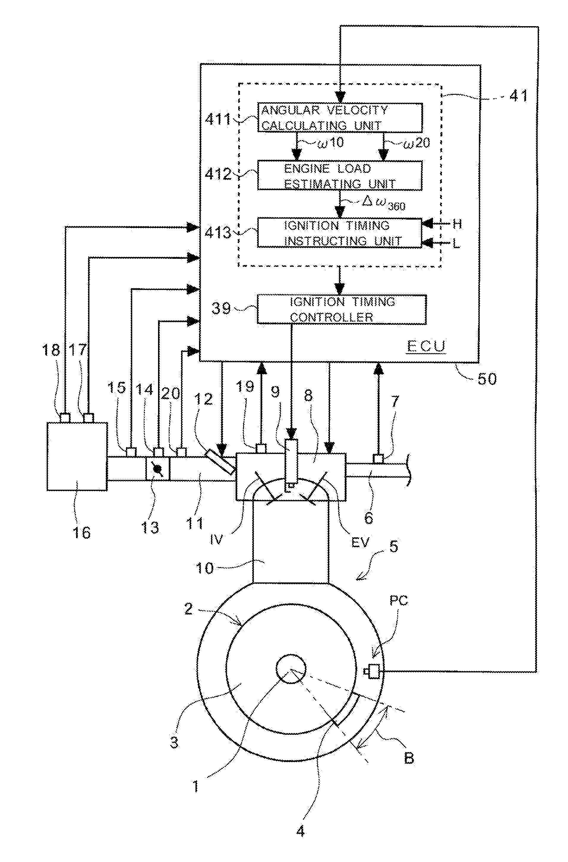
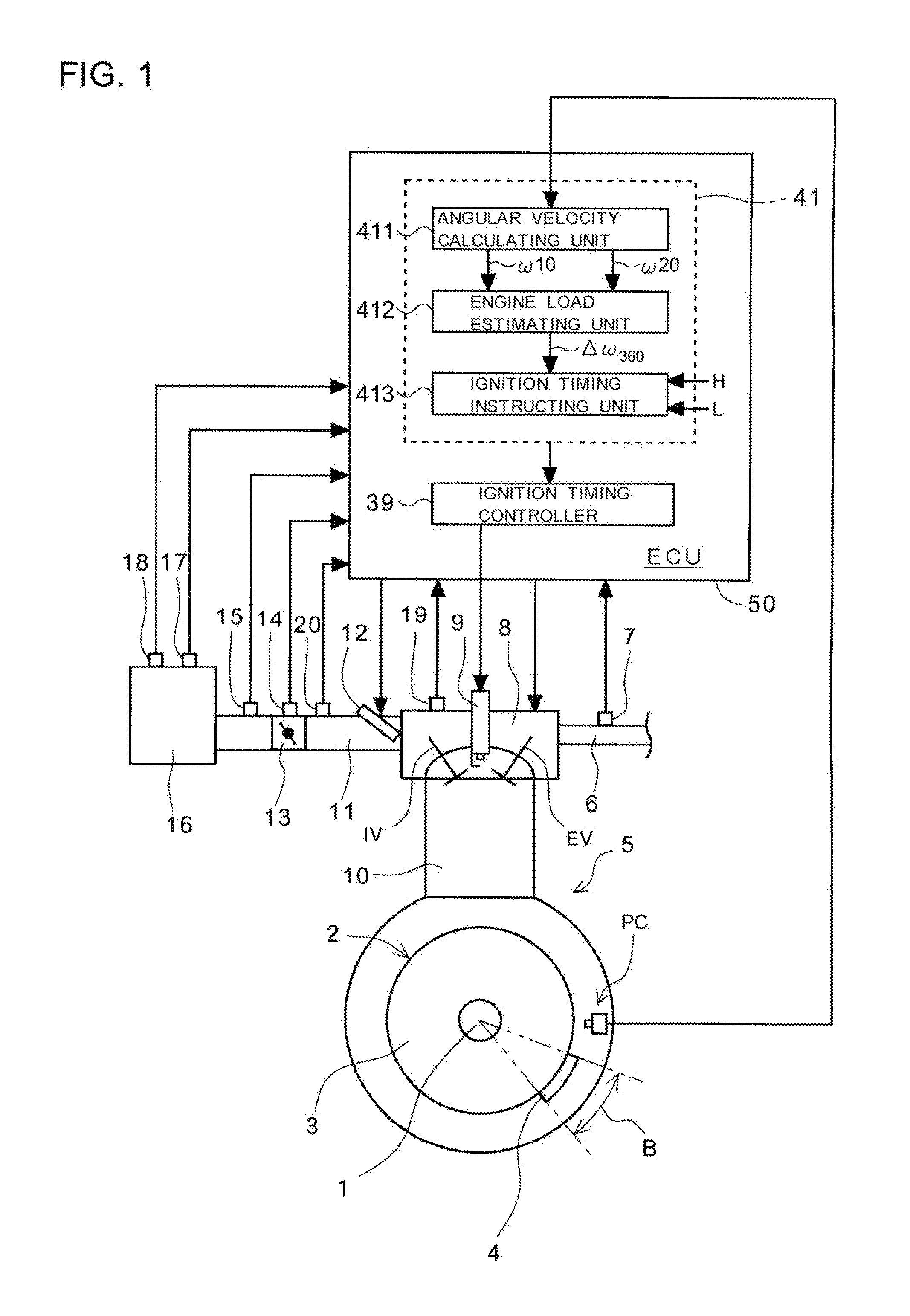
[0024]Hereinafter, a preferred embodiment of the present disclosure will be described in detail with reference to the accompanying drawings. FIG. 1 is a block diagram illustrating the system configuration of an engine control unit according to an embodiment of the present disclosure.

[0025]Referring to FIG. 1, a cylinder head 8 is attached to an upper portion of a cylinder 10 of a four-stroke single-cylinder engine 5. The engine 5 can include a variable valve timing (VVT: Variable Valve Timing) mechanism. The VVT mechanism drives a control motor, not shown, based on drive commands from an ECU 50 to thereby change the valve timing of an intake valve IV and an exhaust valve EV. Along with the change of the valve timing, a valve lift amount also changes. A variable state of the valve timing performed by the VVT mechanism is transmitted to the ECU 50 by a sensor 19 for detecting a rotational angle of the control motor, etc.

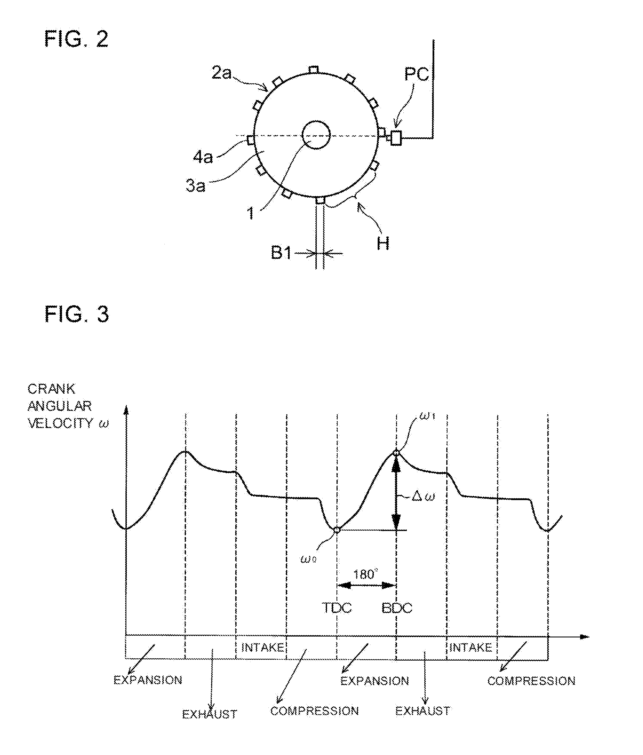
[0026]A crank pulser rotor 2 is mounted on a crankshaft 1 of the ...


PUM


Abstract

To prevent a reduction in engine load detection accuracy due to variations in reluctor size within mass production tolerances, an engine control unit includes a pulse generator PC that detects a reluctor to output crank pulses. An angular velocity calculating unit calculates a first crank angular velocity on the basis of an interval between two crank pulses output in a predetermined section near compression top dead center TDC, and detects near overlap top dead center OLP the same reluctor used for calculating the first crank angular velocity to calculate a second crank angular velocity on the basis of an interval between generated two crank pulses. An engine load estimating unit calculates, as an engine load, a difference between the first crank angular velocity and the second crank angular velocity. The engine load is indicated mean effective pressure over a whole cycle including negative work done by the engine.

Description

TECHNICAL FIELD[0001]This application claims the benefit of priority of Japanese Application No. 2010-282089 filed on Dec. 17, 2010.[0002]The present disclosure relates to an engine control unit, and more particularly, to an engine control unit suitable for improving detection accuracy of the angular velocity of a crankshaft to accurately estimate an engine load.BACKGROUND OF THE INVENTION[0003]When combustion is performed in a cylinder, the angular velocity of a crankshaft is increased from a first angular velocity ωa to a second angular velocity cob by combustion pressure. Therefore, when I represents the rotational moment of inertia of an engine, kinetic energy E increases from (½)·Iωa2 to (½)·Iωb2. In other words, torque is produced according to an increasing amount of this kinetic energy, ΔE=(½)·I·(ωb2−ωa2), and hence the produced torque is proportional to (ωb2−ωa2).[0004]In this manner, the produced torque is obtained from the difference between the square of the first angular...

Claims


Application Information

Patent Timeline
IPC IPC(8): G06F19/00G01M15/05
CPCF02D41/0097F02D41/1497F02P5/151F02D2200/1004G01D5/147G01D5/24428G01P3/488
Inventor NISHIDA, KENJIKANEKO, TETSUYASASAKI, TOMIYUKIAOKI, KOJIIMAO, RANJUFUKUZAWA, KAZUTO
Owner HONDA MOTOR CO LTD
Why Eureka
Try Eureka