

Thermoelectric conversion module and production method therefor
a technology of thermal conversion module and production method, which is applied in the manufacture/treatment of thermoelectric devices, thermoelectric devices with peltier/seeback effect, electrical apparatus, etc., can solve the problems of low power density and low energy conversion efficiency of power generation systems, fracture at the bonding portion between, and leakage of soft soldering materials, so as to reduce the difference in amount, prevent fracturing, and heat and electricity are efficiently conducted
- Summary
- Abstract
- Description
- Claims
- Application Information
AI Technical Summary
Benefits of technology
Problems solved by technology
Method used
Image

Examples
first example
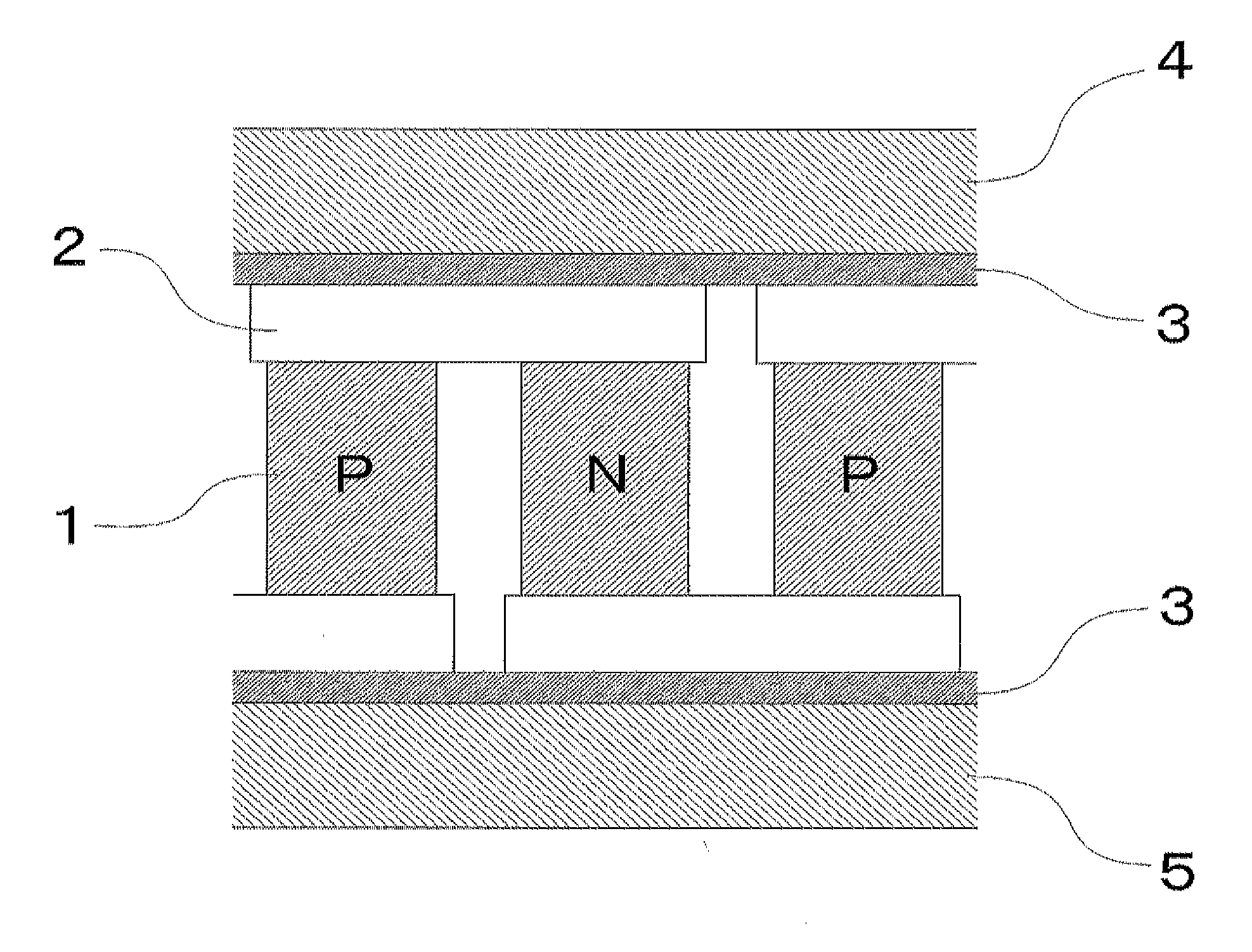
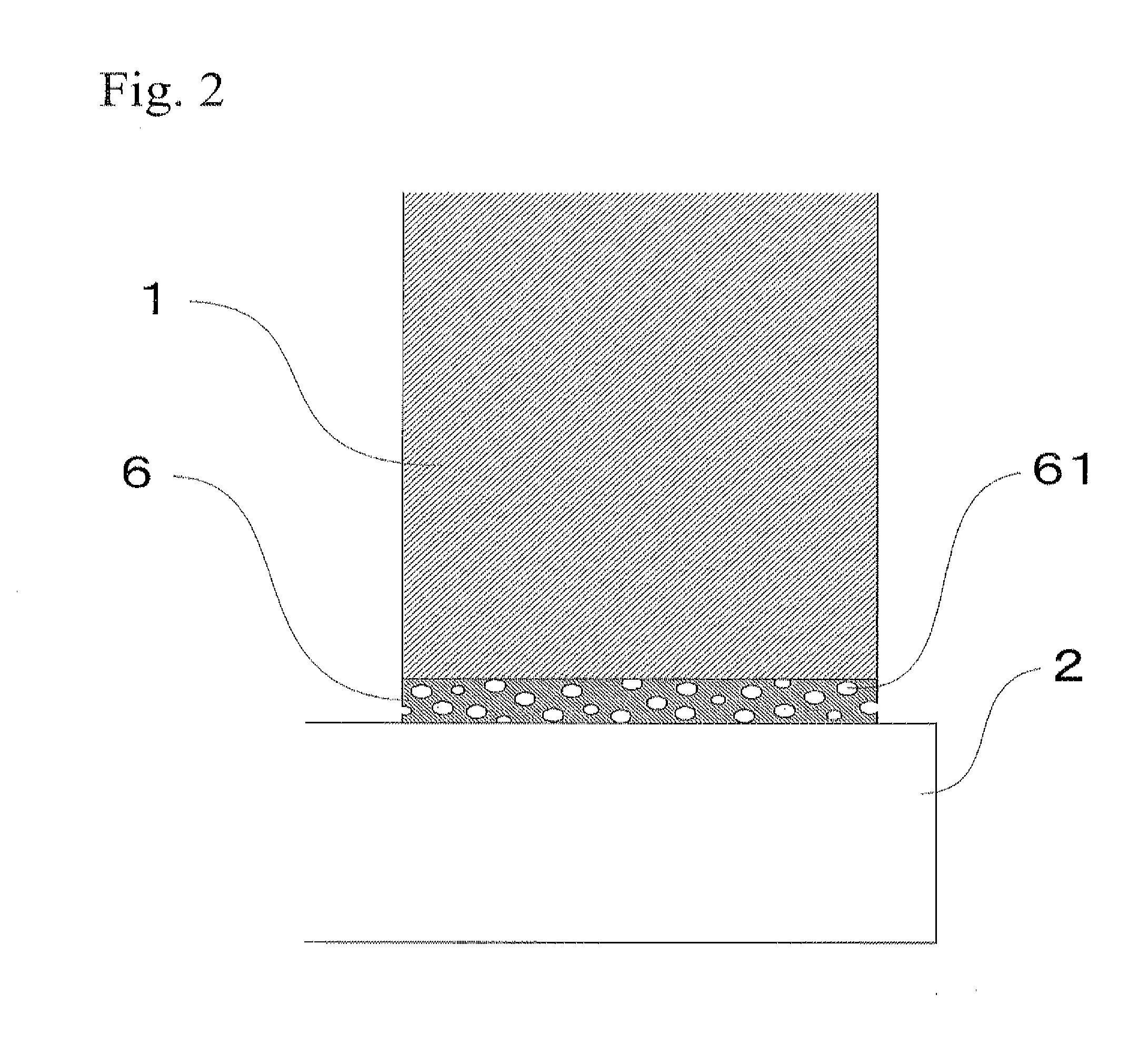
[0043]Nickel powder particles having an average particle diameter of 1 μm and a maximum particle diameter of not more than 10 μm were prepared. Then, 35 volume % of the nickel powder particles were dispersed in normal methyl pyrolidone including 8 volume % of hydroxyl propyl cellulose, whereby a paste was prepared. The paste had a viscosity of approximately 40 Pa·s. The paste was applied to both end surfaces of a thermoelectric conversion element made of silicon germanium. The both end surfaces of the thermoelectric conversion element were abutted with electrodes made of molybdenum. Then, the paste was arranged between the thermoelectric conversion element and the electrode, whereby a thermoelectric conversion module was assembled. A weight of 50 g (corresponding to 1 kPa) was applied to the thermoelectric conversion module and it was placed in a sintering furnace. The thermoelectric conversion module was heated at 500° C. in a hydrogen gas atmosphere so as to remove the paste excep...
second example
[0050]The thermoelectric conversion element used in the First Example was changed to a thermoelectric conversion element made of Mg2Si, in which both end surfaces were covered with nickel. This thermoelectric conversion element was prepared as follows. First, a bulk sintered compact made of Mg2Si was prepared. The bulk sintered compact was plated with nickel and was cut into the shape of the thermoelectric conversion element. Then, a thermoelectric conversion module was made and was evaluated as in the case of the First Example. As a result, although the thermoelectric conversion element was changed, when the density ratio of the porous metal layer was 50 to 90%, the thermal stress was sufficiently decreased, and good bonding condition was maintained. In addition, by performing sintering at 650 to 850° C., the above density ratio was obtained.
third example
[0051]Several kinds of nickel powder particles having an average particle diameter shown in Table 2 were prepared, and pastes were made as in the case of the First Example. Then, thermoelectric conversion modules were assembled by using the pastes as in the case of the First Example. The thermoelectric conversion modules were sintered at 800° C. so as to remove the paste except for the metal powder particles, and to sinter and diffusion bond the metal powder particles as in the case of the First Example. Accordingly, two sets of samples of the thermoelectric conversion modules of the sample Nos. 08 to 13 were prepared. In these samples, the density ratio of the porous metal layer was measured, and the bonding portion before and after the heat test was evaluated. These results are also shown in Table 2.
TABLE 2Densityratio ofMetal powder particles μmporous metalBonding conditionSampleAverageMaximumlayerBeforeAfterNo.particle sizeparticle size%heat testheat test080.0110.096∘x090.110.09...
PUM
 Abstract
Description
Claims
Application Information