RFID transponder and method for operating the same

a transponder and transponder technology, applied in the field of rfid transponders, can solve the problem that the rfid transponder consumes much more power

Active Publication Date: 2012-06-28
TEXAS INSTR INC
View PDF4 Cites 35 Cited by
  • Summary
  • Abstract
  • Description
  • Claims
  • Application Information

AI Technical Summary

Benefits of technology

[0007]It is a general object of the invention to provide an RFID transponder, a method for operating the same and a vehicle keyless entry system comprising an RFID transponder, wherein the RFID transponder is improved with respect to its power consumption.
[0012]In an empirical analysis, it has been discovered that the RFID transponder according to the invention is very tolerant to interference. It has a lower error rate when switching from a sleep mode to the wake up pattern detection mode. In other words, it does least often wrongly switch to the wake up pattern detection mode when—in reality—no wake up pattern has arrived. Accordingly, less power is wasted for untrue startup sequences that do not lead to a successful detection of a wake up burst. The RFID transponder is further robust against various interferences such as strong burst noise, pure random noise or a permanent interfering carrier.
[0014]According to another aspect of the invention, the step size of a big step-down is equal to: twice the step size of a big step-up, four times the step size of a medium step-down, eight times the step size of medium step-up and sixteen times the step size of a small step-up or step-down. The given ratios between the step sizes lead to a binary search algorithm that gives the fastest settling. However, for a given maximum oscillation of the RF-signal level and a given input dynamic range, the number of the required step sizes may be higher than the five step sizes mentioned above. However, this would lead to a more complex control unit. Further, the maximum step size is limited by the speed of the rectifier and peak detector. Empirically, it was found that the above-mentioned ratios between the different step sizes give a good tradeoff between the settling time and an acceptable complexity of the control unit. However the ratio of the step size may also deviate from the above-mentioned factor of two, while also taking into account reasons like complexity of the control unit and speed limitations. Further, the factor between the step sizes may be chosen below a factor of two for big steps due to speed limitations. On the other hand, the factor may be chosen greater then two for small and / or medium step sizes. This leads to more steps but results in a better accuracy of the gain control.
[0015]In another embodiment, the RFID transponder comprises a peak detector coupled to detect a peak level of the amplified RF-signal. The peak detector further communicates the peak level to the control unit, wherein the peak detector has a predetermined high and low detection speed. The control unit is further configured in that the states of the third group cause the peak detector to work at a low detection speed. The third group of states comprises step-up and step-down having a small step size. The attenuator gain is changed very little. Accordingly, the amplified RF-signal will also change very moderately. This allows the peak detector to be set at a low detection speed.
[0016]According to another embodiment of the invention, the second group of states comprises at least two subgroups of states, wherein each subgroup comprises at least a step-up and a step-down. The first sub-group comprises step-up and step-down states having a big step-size, while the second subgroup comprises step-up and step-down states having a medium step size. The control unit is further configured to activate a step-down before activating a step-up, upon wakeup of the RFID transponder. According to embodiment of the invention, the control unit is further configured to activate the states having a big step size before activating states having a medium step size, again upon wakeup of the RFID transponder. The two aforementioned embodiments provide a fast settlement of the amplifier gain upon wakeup of the RFID transponder.
[0024]The power consumption of the RFID according to the invention is minimized. The energy for powering up the second stage of the wake up pattern detector is saved if detection of the first part of the wake up pattern fails.

Problems solved by technology

In this activated state, the RFID transponder consumes much more power.

Method used


Image

  • RFID transponder and method for operating the same
  • RFID transponder and method for operating the same
  • RFID transponder and method for operating the same

Examples


Embodiment Construction

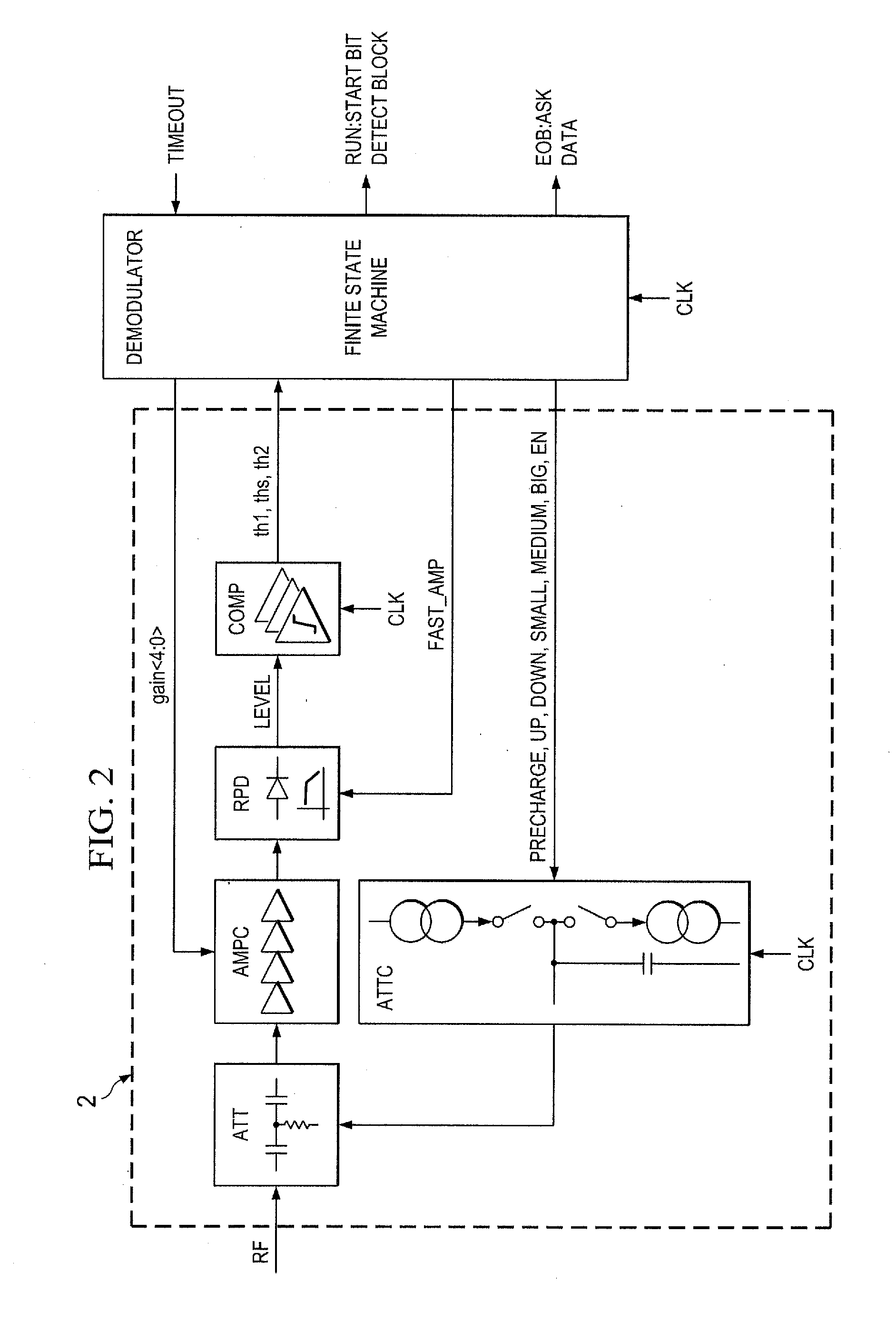
[0037]FIG. 2 is a simplified circuit diagram for an analog front end 2 is a simplified circuit diagram for an analog front end 2 and a digital finite state machine FSM of an RFID transponder. An RF-signal RF that is received by a suitable antenna is coupled to an attenuator ATT. The attenuated signal is subsequently coupled to an amplifier chain AMPC that is working with a fixed amplification gain. The attenuation factor of the attenuator ATT is controlled by an attenuator controller ATTC. The overall amplification gain of the RF-signal is controlled by controlling the attenuation factor of the attenuator ATT. Since the amplification factor of the amplifier chain AMPC is constant, the total gain for the RF-signal solely depends on the attenuation factor that is the reciprocal value of the amplifier gain. In the following, the term attenuator gain will be used for this reciprocal attenuation factor that is further proportional to the overall gain of the RF-signal. Accordingly, the ga...


PUM


Abstract

An RFID transponder having an analog front end receiver having an attenuator coupled to receive an RF-signal from an antenna and to attenuate the RF-signal, an amplifier having a fixed amplifier gain and being coupled to receive and to amplify the attenuated RF-signal and a control unit coupled to control a gain of the attenuator, wherein the control unit is configured to control the attenuator gain in response to a level of the amplified RF-signal, the control unit is configured to have a plurality of predetermined states causing the attenuator to increase (step-up) or to decrease (step-down), its gain by a predefined step size.

Description

CROSS-REFERENCE TO RELATED APPLICATIONS[0001]This patent application claims priority from German Patent Application No. 10 2010 055 470.7, filed Dec. 22, 2010, which is incorporated herein by reference in its entirety.FIELD OF THE INVENTION[0002]The invention relates to an RFID transponder and to a method for operating the same. The invention relates to a vehicle keyless entry system comprising a base station and the RFID transponder.BACKGROUND OF THE INVENTION[0003]RFID transponders are used in numerous applications such as identification or passive keyless entry systems. A field of application is a road vehicle keyless entry system. Such an entry system uses RF-signals in the frequency range of about 120 kHz to 140 kHz. Typically, a base station transmitter that is located in the car sends a short sequence of symbols as digitally modulated RF-signals. A known method of modulation is amplitude shift keying. A mobile transponder that is typically a part of a car key receives these R...

Claims


Application Information

Patent Timeline
Patent Type & Authority Applications(United States)
IPC IPC(8): G06K7/01G06K19/073
CPCG07C2009/00373H03G3/3052G07C2009/00793G07C9/00309G06K7/10128G06K7/10158
Inventor MUELLNER, ERNSTPESCHKE, CARLO
Owner TEXAS INSTR INC
Why Eureka
Try Eureka