Burst-Mode Receiver Equipped with Optical Amplifier, Method for Controlling Optical Amplifier, and System

a technology of optical amplifier and burst-mode receiver, which is applied in the field of optical receiver section equipped with optical amplifier, can solve the problems of limiting the range of optical strength that can be received, the dependence of the wavelength of each onu, and the inability to compensate the gain dependency, so as to keep the receivable range of the receiver in a wide state, the effect of polarization dependence and almost constant optical amplifier gain

Inactive Publication Date: 2012-06-28
HITACHI LTD
View PDF13 Cites 31 Cited by
  • Summary
  • Abstract
  • Description
  • Claims
  • Application Information

AI Technical Summary

Benefits of technology

[0020]The optical receiver section can keep the gain of the optical amplifier almost constant without depending on the wavelength even when the wavelength of the received burst signal varies for every ONU. Therefore, even in the case where the wavelength varies for every ONU and the gain of the optical amplifier is dependent on the wavelength or polarization direction, it is possible to keep the receivable range of the receiver in a wide state.
[0021]Moreover, even in the case where the wavelength dependency and the polarization dependency of the low-cost optical amplifier are large, since the receivable range does not deteriorate, it becomes possible to use the low-cost optical amplifier. Therefore, it is possible to lower a production cost in the OLT equipped with the optical amplifier.

Problems solved by technology

In the PON system, the wavelengths of respective ONU's are not generally managed, and therefore the gain dependency on the wavelength of each ONU cannot be compensated.
Performance of the optical receiver in the later stage restricts a range of optical strength that can be received by the optical receiver in the later stage.

Method used


Image

  • Burst-Mode Receiver Equipped with Optical Amplifier, Method for Controlling Optical Amplifier, and System
  • Burst-Mode Receiver Equipped with Optical Amplifier, Method for Controlling Optical Amplifier, and System
  • Burst-Mode Receiver Equipped with Optical Amplifier, Method for Controlling Optical Amplifier, and System

Examples


first embodiment

[Configuration of General PON System]

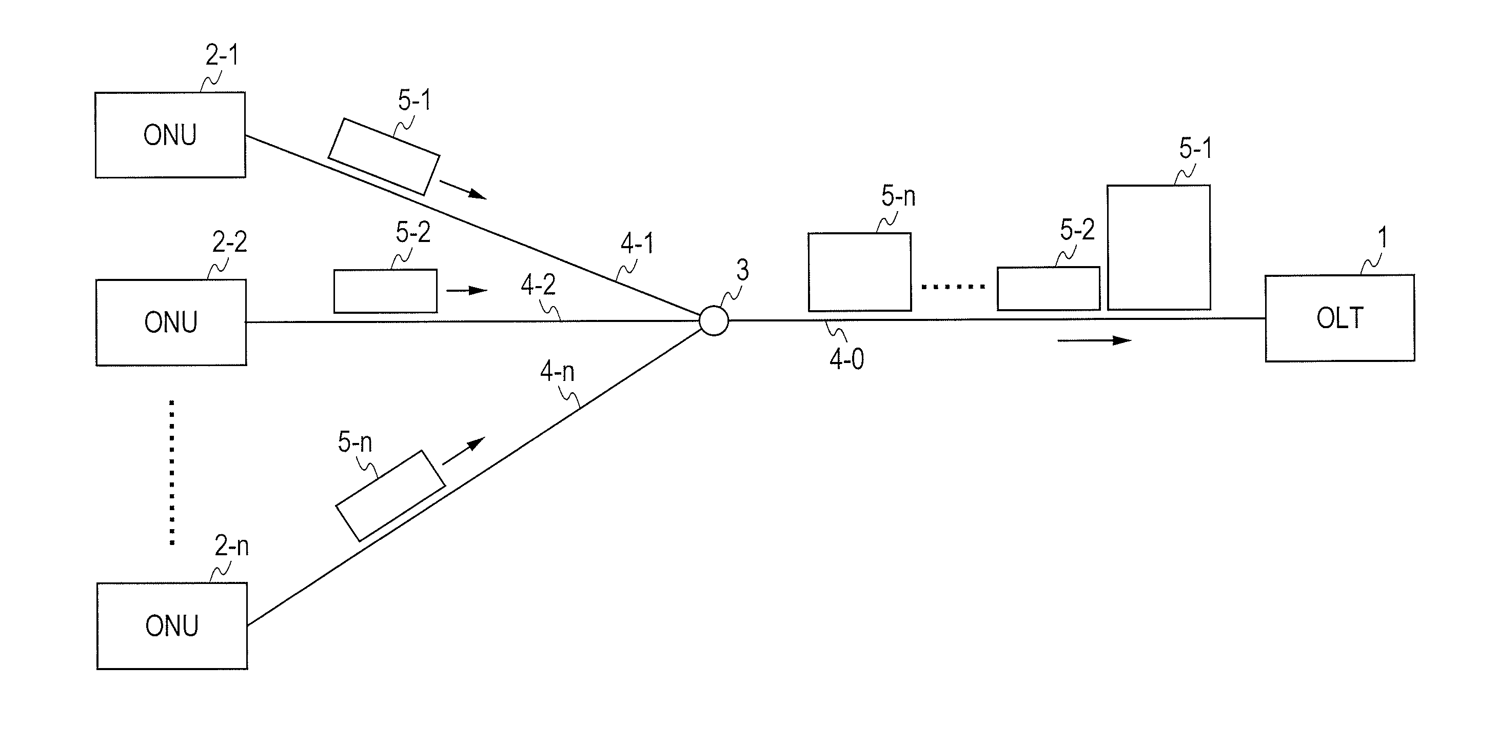
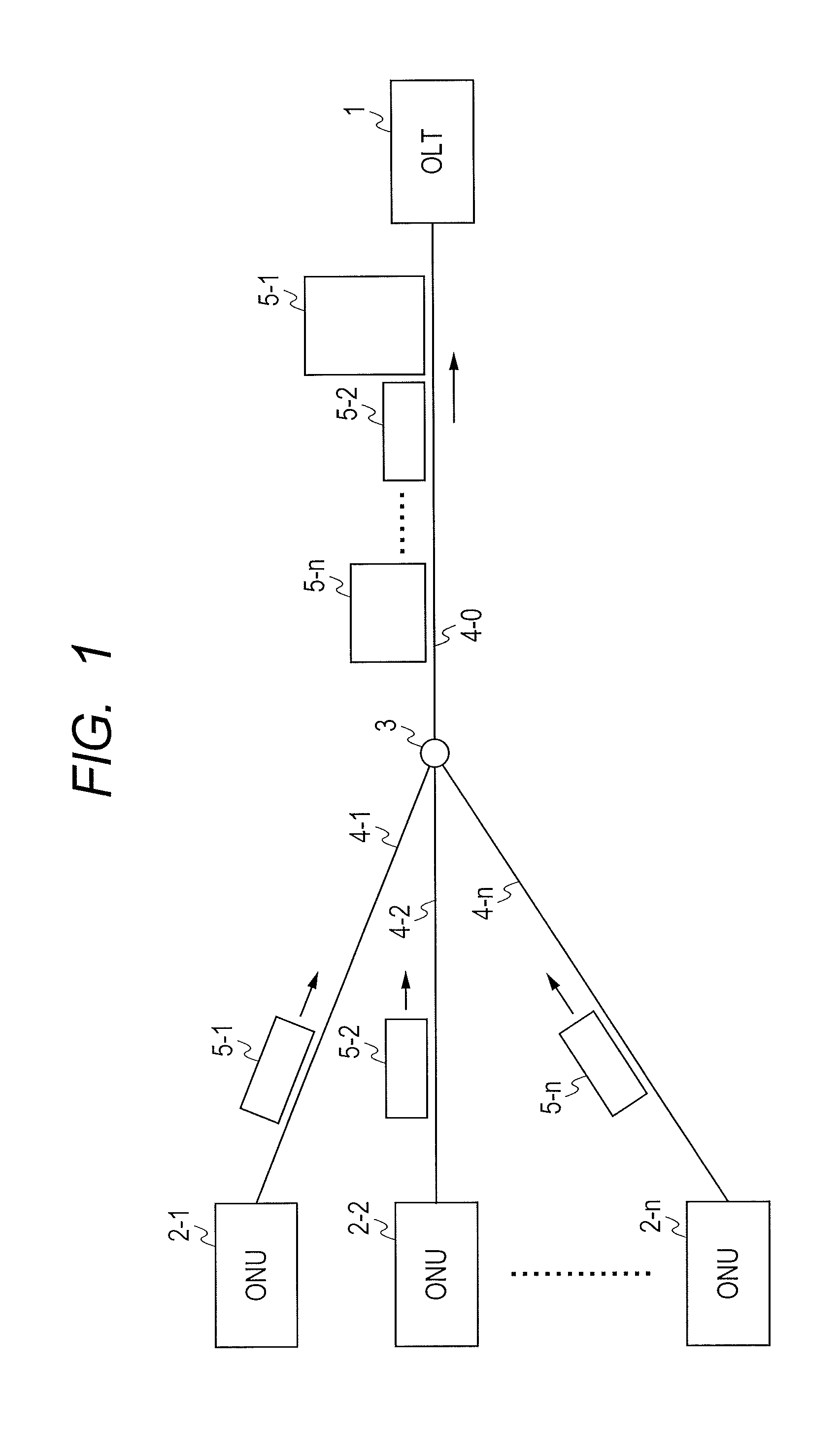
[0053]FIG. 1 shows a configuration of the optical access network using PON. The optical access network has OLT1, an optical splitter 3, and multiple ONU2's (2-1 to 2-n). The OLT1 is connected with the optical splitter 3 through optical fiber 4-0 that is of a trunk line. ONU2's (2-1 to 2-n) are connected to the optical splitter 3 through the optical fibers 4 (4-1 to 4-n) of branch lines, respectively. Uplink transmission to the OLT1 from ONU2's (2-1 to 2-n) will be explained. The optical signals that ONU2's sent out are multiplexed by the optical splitter 3. The multiplexed optical signal is inputted into the OLT1. The distance between ONU2 and the OLT1 differs for every ONU. Moreover, since the optical signal attenuates as the distance increases, the optical signal inputted into the OLT1 becomes a burst signal whose strength varies.

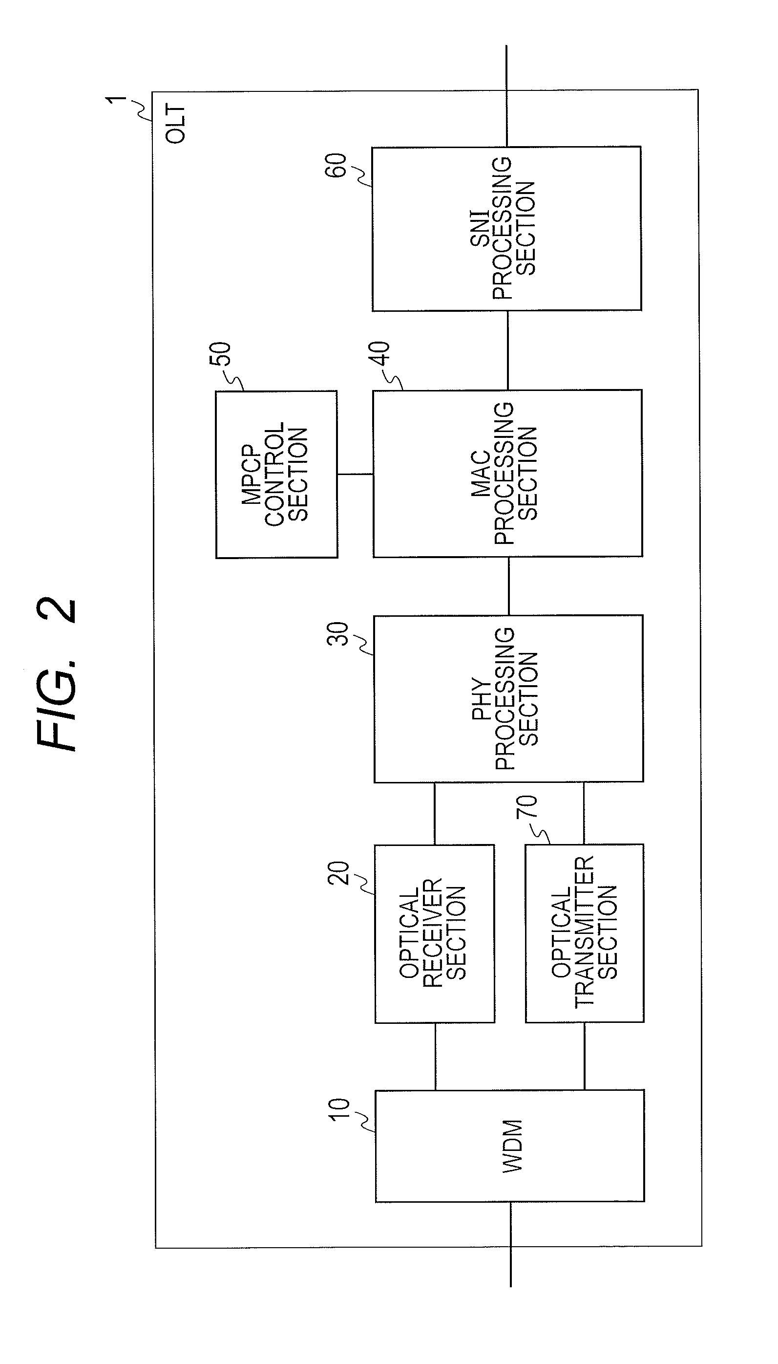
[Configuration of General OLT]

[0054]FIG. 2 shows a configuration of an OLT1 device. The OLT1 includes a WDM 10, an o...

second embodiment

[0090]Next, a second embodiment of the present invention will be described. The explanation will be given focusing on a difference with respect to the first embodiment. In the second embodiment, the optical receiver section has a variable attenuator, and an amount of attenuation of the variable attenuator is adjusted for every transmission wavelength of the ONU.

[Configuration of Optical Receiver Section in the Second Embodiment]

[0091]A configuration of an optical receiver section in a second embodiment will be explained using FIG. 14. Differences with respect to the first embodiment exist in a point of having a variable attenuator 212 and a point that an optical amplifier control section 242 can control the amount of attenuation of the variable attenuator 212.

[0092]The variable attenuator 212 attenuates the optical signal that was inputted from the optical amplifier 210 based on the amount of attenuation directed by the optical amplifier control section 242, and outputs the attenuat...

third embodiment

[0100]Next, a third embodiment of the present invention will be described. The explanation will be given focusing on a difference with respect to the first embodiment. In the third embodiment, instead of negating the need for the ONU wavelength management section, a wavelength detection section is provided, a wavelength is detected from the received optical signal, and the injection current of the optical amplifier is adjusted based on the detected wavelength.

[Configuration of Optical Receiver Section in the Third Embodiment]

[0101]FIG. 16 shows a configuration of an optical receiver section 20 in the third embodiment of the present invention. Differences with respect to the first embodiment are a point of not having the ONU wavelength management section and a point of having an optical splitter 280, an optical spectrum detector 281, and a wavelength detection section 282. Moreover, this configuration includes an optical amplifier control section 243 and an MPCP control section 52 th...


PUM


Abstract

To, even when a transmission wavelength varies in each ONU and an optical amplifier gain depends on the wavelength in an OLT equipped with an optical amplifier, prevent the optical amplifier gain from varying in every ONU and thus prevent deterioration of a dynamic range. The OLT estimates a transmission wavelength of each ONU at the time of ONU registration, and retains a correspondence between an ONU identifier and the transmission wavelength. Moreover, for every burst, an injection current to the optical amplifier is adjusted based on a wavelength and optical amplifier characteristic database.

Description

CLAIM OF PRIORITY[0001]The present application claims priority from Japanese patent application JP 2010-289128 filed on Dec. 27, 2010, the content of which is hereby incorporated by reference into this application.FIELD OF THE INVENTION[0002]The present invention relates to an optical line terminal (OLT) in a Passive Optical Network, and more specifically, to an optical receiver section equipped with an optical amplifier.BACKGROUND OF THE INVENTION[Spread of Optical Access Networks][0003]In recent years, a demand to improvement in the speed to networks increases with spread of the Internet, and popularization of ADSL (Asymmetric Digital Subscriber Line), B-PON (Broadband PON), E-PON (Ethernet PON), and G-PON (Gigabit Capable PON) is progressing are progressing. Especially in the PON system, in connecting an optical line terminal (OLT) placed in a telephone company's local office and an optical network unit (ONU) placed in each user premises, the OLT extends therefrom one strand of f...

Claims


Application Information

Patent Timeline
Patent Type & Authority Applications(United States)
IPC IPC(8): H04J14/02H04B10/08H04J14/06H04B10/27H04B10/07H04B10/272H04B10/293H04B10/40H04B10/50H04B10/60H04B10/66
CPCH04B10/272
Inventor SUGAWA, JUNIKEDA, HIROKIKAZAWA, TOHRU
Owner HITACHI LTD
Why Eureka
Try Eureka