Integrated pump, coolant flow control and heat exchange device

a technology of integrated pump and heat exchange device, which is applied in the direction of machines/engines, combustion air/fuel air treatment, light and heating apparatus, etc., can solve the problems of transmission oil cooler not fully utilizing the maximum cooling potential available for transmission oil cooling, transmission to be overheated and damaged, and the temperature of the cooling valve does not increase more rapidly, so as to improve the fuel economy and heat exchange management. , the effect of speeding up the oil warm-up and reducing the temperature of the cooling

Inactive Publication Date: 2012-07-05
HYUNDAI MOTOR CO LTD +2
View PDF19 Cites 18 Cited by
  • Summary
  • Abstract
  • Description
  • Claims
  • Application Information

AI Technical Summary

Benefits of technology

[0013]In its broadest aspects, the present invention features an integrated coolant delivery, flow control and heat exchange device which pumps or delivers coolant to an engine while controlling multiple flow modes and coolant paths to branch out (or converge) from (or to) a coolant flow valve which in turn controls all paths of coolant flow through a heat exchange mixing box. Such an integrated coolant delivery, flow control and heat exchange device should improve both fuel economy and management of heat exchange between components of a vehicle using such a device. More particularly, such improvement is expected when using the device of the present invention for a number of reasons including, for example, (a) optimizing flow control speed to actual needs rather than engine speed; (b) keeping the pump off on cold start; (c) allowing interior heating with engine coolant rather than electric auxiliary heat on shutdown (start-stop for hybrids); (d) allowing faster oil warm-up (both engine & transmission); (e) allowing faster cold engine warm-up (optimize coolant flow); (f) reducing water pump load (minimize high flow pressure drop); (g) improving temperature control (minimize coolant and engine oil temperature variation within engine and increase cold weather transmission oil operating temperatures (“Oil heating mode in cold weather conditions”); and / or (h) allowing for engine coolant operating temperature calibration for optimum efficiency at any operating condition through engine control module.

Problems solved by technology

The coolant control valve, however, does not provide a more rapid increase in the temperature of the transmission oil circuit because of positional limitation of a transmission oil cooler.
Accordingly, as the coolant flows through multiple coolant circuits, the transmission oil cooler is not fully utilizing the maximum cooling potential available for transmission oil cooling.
In case of the air to oil transmission oil cooler, if there is not a temperature bypass valve in the flow circuit, the oil in the cooler can get so cold and thick that the oil cooler may freeze and may not ever allow oil to pass through the cooler and, in some cases, may cause the transmission to be overheated and be damaged due to no oil flow through the transmission oil cooler.
An additional parasitic loss to the engine fuel economy performance is the engine driven mechanical water pump.
Some vehicles have recently introduced an electric water pump on an internal combustion engine but this design traditionally has been avoided due to vehicle electrical power limitations due to the high current draw required to support a stand alone water pump capable of flowing enough coolant to properly cool the vehicle.

Method used


Image

  • Integrated pump, coolant flow control and heat exchange device
  • Integrated pump, coolant flow control and heat exchange device
  • Integrated pump, coolant flow control and heat exchange device

Examples


Embodiment Construction

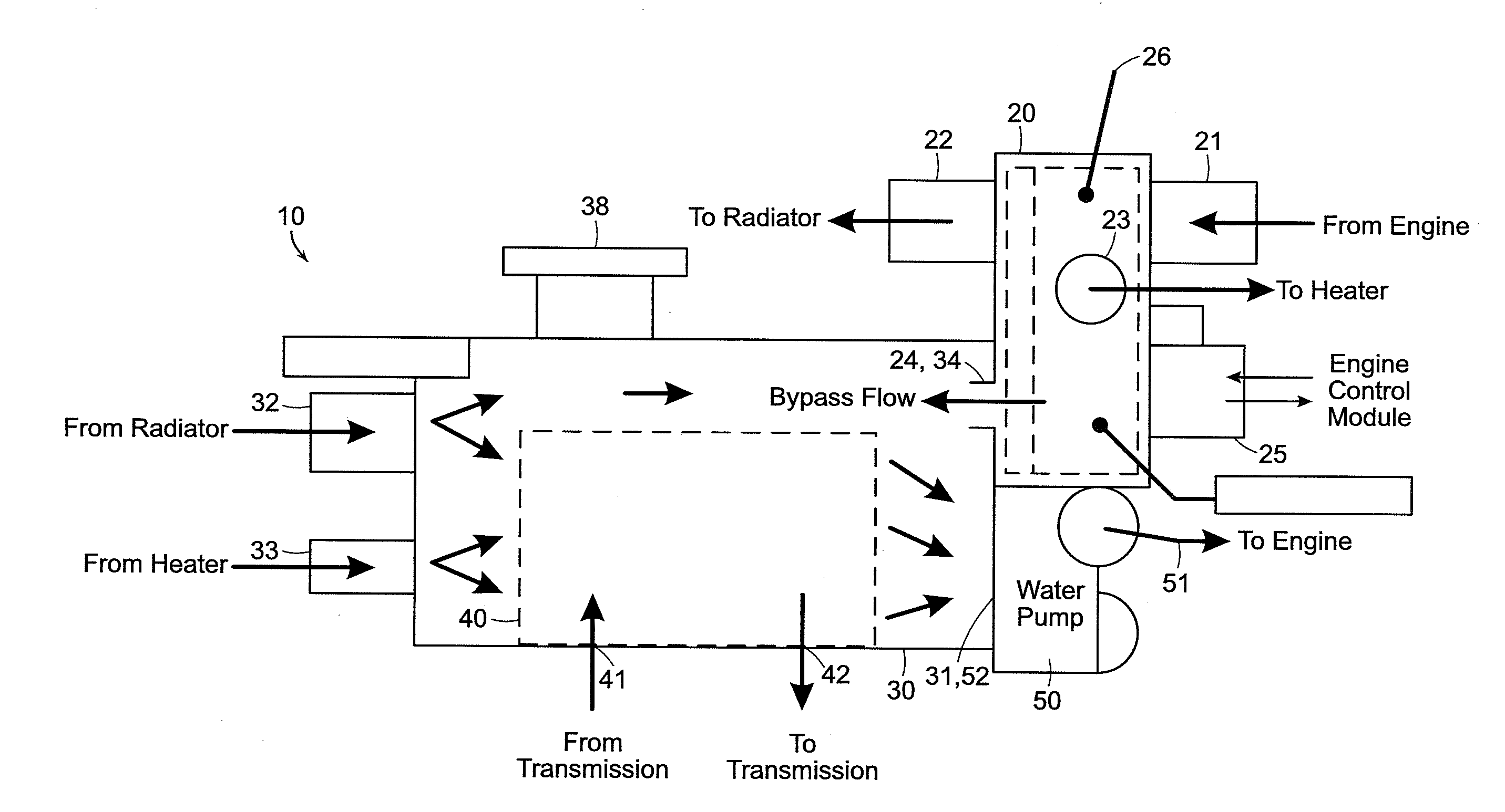
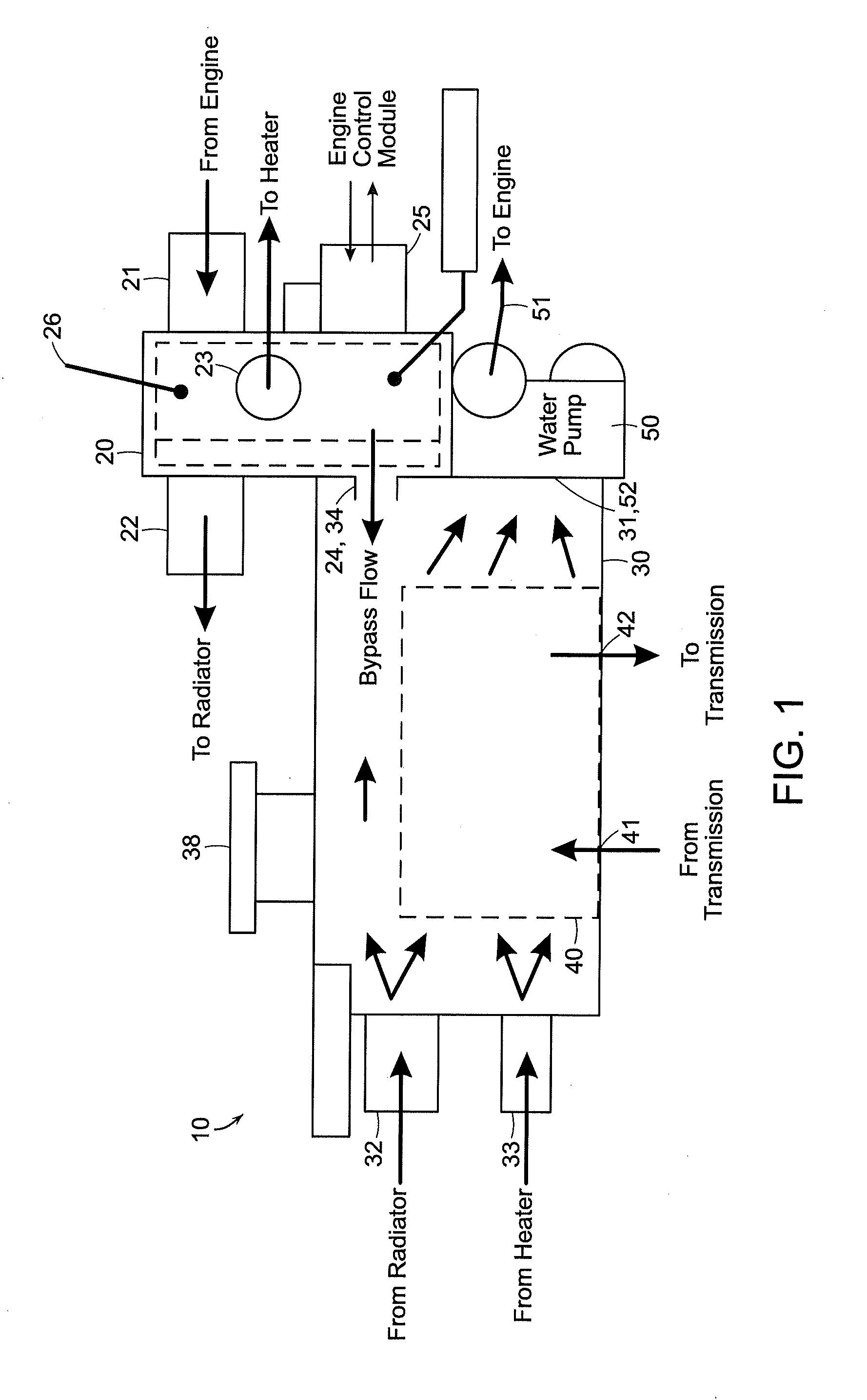
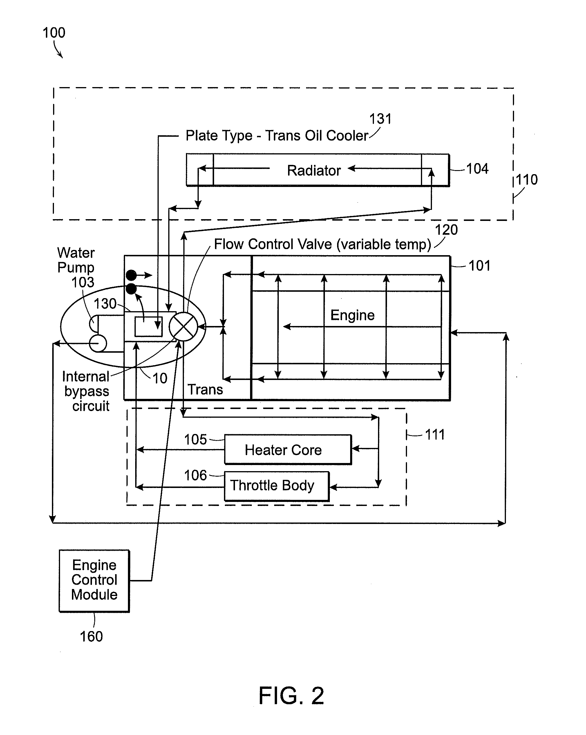
[0042]As discussed above, we now provide an integrated coolant delivery, flow control and heat exchange system and an integrated pump, flow control and heat exchange device. Such systems or devices in their broadest aspects, pump or deliver coolant to an engine while controlling multiple flow modes and coolant paths to branch out (or converge) from (or to) a coolant flow valve which in turn controls all paths of coolant flow through a heat exchange mixing box. In more particular aspects, such systems and devices of the present invention, comprises an integrated pump for delivering an engine coolant to the engine, coolant flow control and heat exchange device for a vehicle.

[0043]Systems and devices of the invention can provide notable advantages over prior systems, including for example, eliminating the need for FEAD (front end assembly drive) mechanically driven impellor / pulley water pump; potentially simplifying and / or eliminating certain connecting tubes, hose and clamp parts; imp...


PUM


Abstract

A coolant flow control system includes an integrated pump for delivering an engine coolant to an engine, coolant flow control and heat exchange device. According to the system, coolant flow from the engine is delivered back to the engine after passing through the valve body part and then the heat exchange part in which it passes over the heat exchange part. Systems of the invention are particularly useful with all-electric and hybrid vehicles.

Description

BACKGROUND[0001](a) Technical Field[0002]The present invention generally relates to systems and devices for delivering a coolant to an engine of a vehicle, such as electric-powered vehicles and hybrid vehicles (e.g., vehicles powered by an electric motor(s) and / or an internal combustion engine). More particularly, the present invention relates to an integrated pump, coolant flow control and heat exchange device and systems embodying same and yet more particularly, to such an integrated pump, flow control and heat exchange device having the ability to simultaneously control flow paths and flow volume.[0003](b) Background Art[0004]Generally, a vehicle includes an engine, a transmission, a unit heater, a radiator, a pump for delivering a coolant to the engine, and an engine control module. A typical cooling system used in a vehicle includes three main flow circuits: an engine bypass circuit, a circuit including a unit heater, and a circuit including a radiator.[0005]Coolant flow may be...

Claims


Application Information

Patent Timeline
Patent Type & Authority Applications(United States)
IPC IPC(8): F28F27/00F01P9/00
CPCB60K11/02F02B29/0475F28F27/02F01P2060/18F01P2050/24F01P2060/045Y02T10/146
Inventor MYERS, JOHN W.BOURCIER, MARK A.
Owner HYUNDAI MOTOR CO LTD
Why Eureka
Try Eureka