Method for producing a perpendicular magnetic recording medium

Active Publication Date: 2012-07-05
WESTERN DIGITAL TECH INC
View PDF3 Cites 71 Cited by
  • Summary
  • Abstract
  • Description
  • Claims
  • Application Information

AI Technical Summary

Benefits of technology

[0023]According to the present invention, separation properties are further improved by composing the intermediate layer of consecutive N layers (provided that N is an integer of at least 3 or more); and depositing a first layer containing ruthenium (Ru) as a main component, first; setting a gas pressure during the deposition to the pressure which is higher than or the same as that in the first layer; depositing a second layer containing ruthenium (Ru), or ruthenium (Ru) containing oxygen or an oxide as a main component; and adjusting

Problems solved by technology

However, in a magnetic disk for an in-plane magnetic recording system (which is also referred to as a longitudinal magnetic recording system, or a horizontal magnetic recording system) commercialized in the related art, progress in reducing the size of the magnetic crystal particl

Method used


Image

  • Method for producing a perpendicular magnetic recording medium
  • Method for producing a perpendicular magnetic recording medium

Examples


example 1

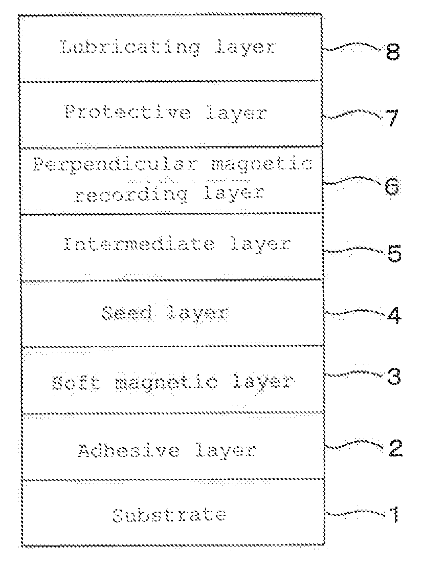
[0049]As shown in FIG. 1, an adhesive layer 2, a soft magnetic layer 3, a seed layer 4, an intermediate layer 5, a perpendicular magnetic recording layer 6, a protective layer 7 and a lubricating layer 8 were deposited on a substrate 1 in that order to produce a perpendicular magnetic recording medium of Example 1. Description is made in detail below.

[0050]An amorphous aluminosilicate glass was molded into a disk shape by direct press to produce a glass disk. The glass disk was cut, polished, and chemically hardened in this order, whereby a flat non-magnetic glass substrate formed of the chemically hardened glass disk was obtained. The diameter of the disk was 65 mm. The surface roughness of the main surface of the glass substrate 1 was measured by an atomic force microscope (AFM) to obtain the following result: Rmax was 2.18 nm, and Ra was 0.18 nm. The thus-obtained substrate was found to have a flat surface. The Rmax and Ra were measured in accordance to Japanese Industrial Standa...

example 2

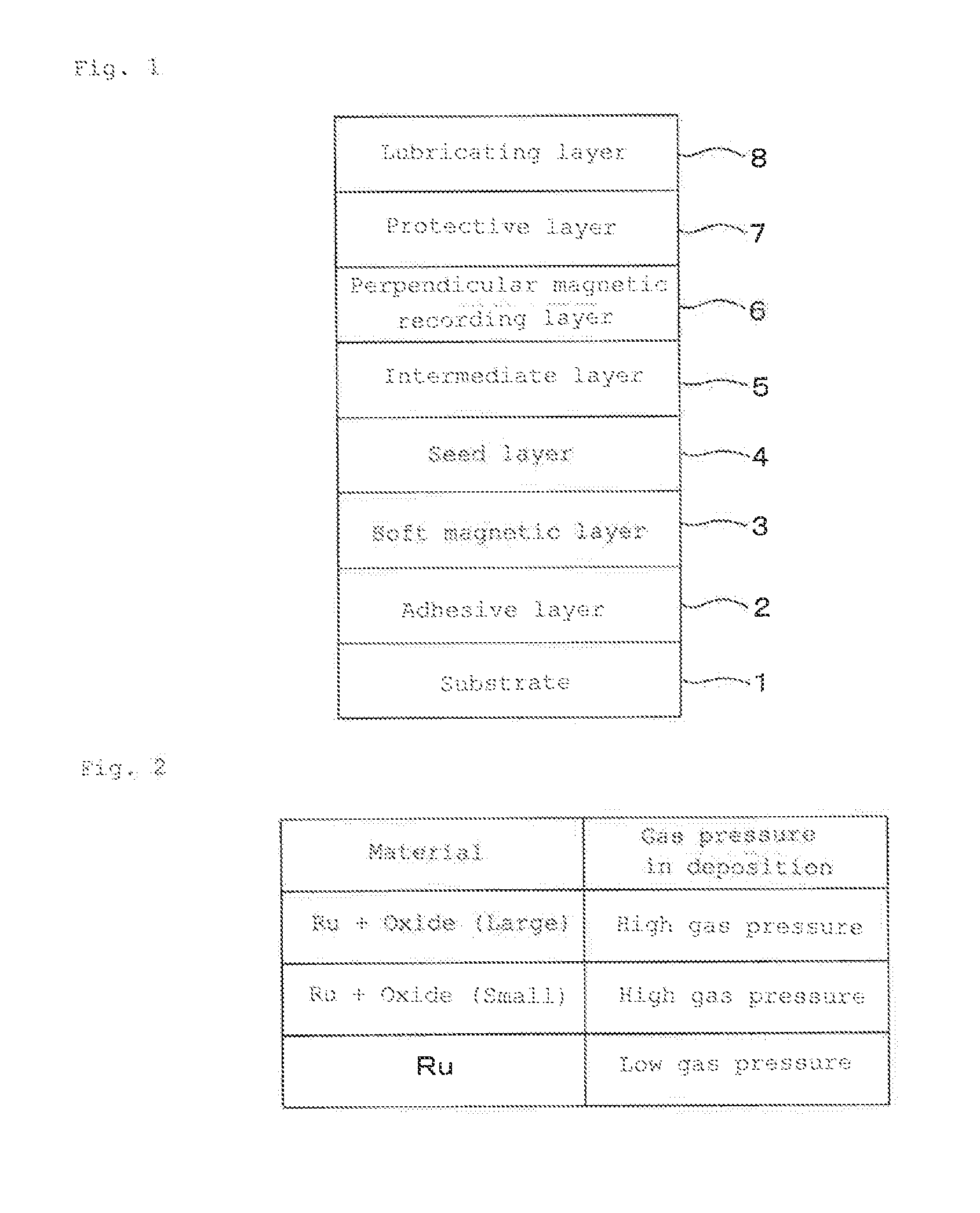
[0060]In the deposition step of the intermediate layer in Example 1, Ru was deposited as the first layer in a thickness of 10 nm by adjusting an Ar gas pressure to 0.7 Pa in the very same manner as in Example 1. Then, Ru—SiO2 was deposited as the second layer in a thickness of 6 nm by adjusting an Ar gas pressure to 4.5 Pa using an Ru—SiO2 (SiO2 (containing 4,000 ppm by weight of oxygen) target. Subsequently, Ru—SiO2 was deposited as the third layer in a thickness of 6 nm by adjusting an Ar gas pressure to 4.5 Pa using an Ru—SiO2 (SiO2 (containing 8,000 ppm by weight of oxygen) target.

[0061]In the same manner as in Example 1, except for changing the deposition of the intermediate layer as described above, a perpendicular magnetic recording medium of Example 2 was obtained.

example 3

[0062]In the deposition step of the intermediate layer in Example 1, Ru was deposited as the first layer in a thickness of 10 nm by adjusting an Ar gas pressure to 0.7 Pa in the very same manner as in Example 1. Then, Ru was deposited as the second layer in a thickness of 6 nm by adjusting an Ar gas pressure to 4.5 Pa and performing Ar (99.5%)+oxygen (0.5%) reactive sputtering using an Ru target. Subsequently, Ru—SiO2 was deposited as the third layer in a thickness of 6 nm by adjusting an Ar gas pressure to 4.5 Pa using an Ru—SiO2 (SiO2 (containing 4,000 ppm by weight of oxygen) target. In the same manner as in Example 1, except for changing the deposition of the intermediate layer as described above, a perpendicular magnetic recording medium of Example 3 was obtained.

[0063]It is recognized that the obtained perpendicular magnetic recording medium exhibits the same characteristics as in oxygen reactive sputtering even in case of using a target of Ru containing oxygen under depositio...


PUM


Abstract

To provide a method for manufacturing a perpendicular magnetic recording medium, which is capable of coping with the much higher recording density.
Disclosed is a method for manufacturing a perpendicular magnetic recording medium to be used for recording information by a perpendicular magnetic recording system, including at least a soft magnetic layer, an intermediate layer, and a magnetic recording layer on a substrate, characterized in that the method includes the step of:
  • composing the intermediate layer of consecutive N layers (provided that N is an integer of at least 3 or more), depositing a first layer containing ruthenium (Ru) as a main component, first; setting a gas pressure during the deposition to the pressure which is higher than or the same as that in the first layer; depositing a second layer containing ruthenium (Ru), or ruthenium (Ru) containing oxygen or an oxide as a main component; and adjusting so that the oxygen content remains constant, or increases toward the uppermost layer in the second layer and succeeding layers.

Description

BACKGROUND OF THE INVENTION[0001]1. Technical Field[0002]The present invention relates to a method for manufacturing a perpendicular magnetic recording medium to be mounted on a magnetic disk device of a perpendicular magnetic recording system, such as a hard disk drive (HDD).[0003]2. Background Art[0004]With increasing capacity for information processing, various types of information recording techniques have been recently developed. In particular, the HDD using a magnetic recording technique has been continuing to increase a surface recording density at a rate of about 100% per year. In recent years, magnetic disks of 2.5 inches in diameter for use in the HDD or the like have been required to have an information recording capacity exceeding 250 Gbyte per piece. An information recording density exceeding 400 Gbit per square inch is required so as to achieve such a requirement. In order to achieve the high recording density in the magnetic disk to be used in the HDD or the like, it ...

Claims


Application Information

Patent Timeline
IPC IPC(8): G11B5/84
CPCG11B5/667G11B5/738G11B5/7325G11B5/8404G11B5/7369
Inventor KOIKE, TAKASHIFURUGORI, SHIGEAKI
Owner WESTERN DIGITAL TECH INC
Why Eureka
Try Eureka