Submerged Perfusion Bioreactor

a bioreactor and submerged technology, applied in the direction of biomass after-treatment, chemical/physical processes, centrifugal force sediment separation, etc., can solve the problems of insufficient transport of simple diffusion, limited clinical application use, and insufficient monolayer culture for cells, etc., to achieve simple setup

Inactive Publication Date: 2012-07-05
CAROUCELL APS
View PDF9 Cites 13 Cited by
  • Summary
  • Abstract
  • Description
  • Claims
  • Application Information

AI Technical Summary

Benefits of technology

[0015]It is the object of the present invention to create a cell culture method which reduces the above mentioned problems. Thus, it is the purpose of this invention to create a compact device which is simple in setup without the need of external pumping mechanisms in order to obtain a perfusion flow system.DESCRIPTION OF THE INVENTION

Problems solved by technology

However, monolayer cultures are not optimal for cells as they do not experience conditions similar to their natural environment.
Even if the differentiation is successful in 2D the usage in clinical applications has been limited, because the architecture of the formed extracellular matrix is diverse from the native tissue morphology.
3D cultures require means of increasing the flow of nutrients and oxygen to the cells and removal of waste products from the cells situated centrally in the scaffold, as simple diffusion is insufficient for transport at distances longer than approx.
The main drawback of this culture method is that the scaffolds are not thoroughly or evenly perfused.
Furthermore, because the viscous flow field around each scaffold is dependent on the exact spatial position in the flask, it is difficult to achieve consistent results when culturing more than 8 samples in one flask.
This is a disadvantage of this method, as it increases the overall footprint of the perfusion setup.
However, these methods have huge drawbacks.
For the perfusion flow, the equipment itself is not ideal since a large amount of tubes are needed in order to sustain a constant flow of liquid medium.
Furthermore, a large amount of equipment like pumps and flasks are arranged inside the incubator, thus taking up large amounts of valuable incubator shelf space.
This system fails to eliminate the need for tubing and comprises a large number of assembly parts.
Furthermore, although the mean flow through the scaffold can be calculated, non-uniformity between individual scaffolds will lead to non-uniform perfusion.

Method used


Image

  • Submerged Perfusion Bioreactor
  • Submerged Perfusion Bioreactor
  • Submerged Perfusion Bioreactor

Examples


Embodiment Construction

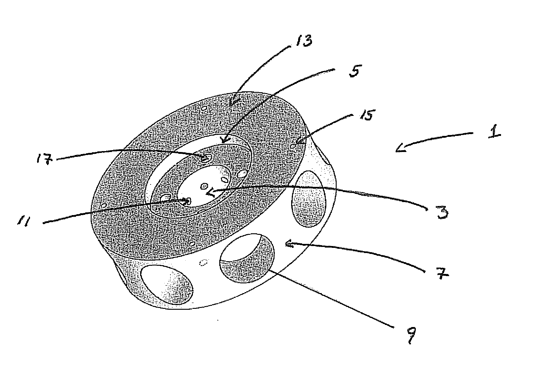
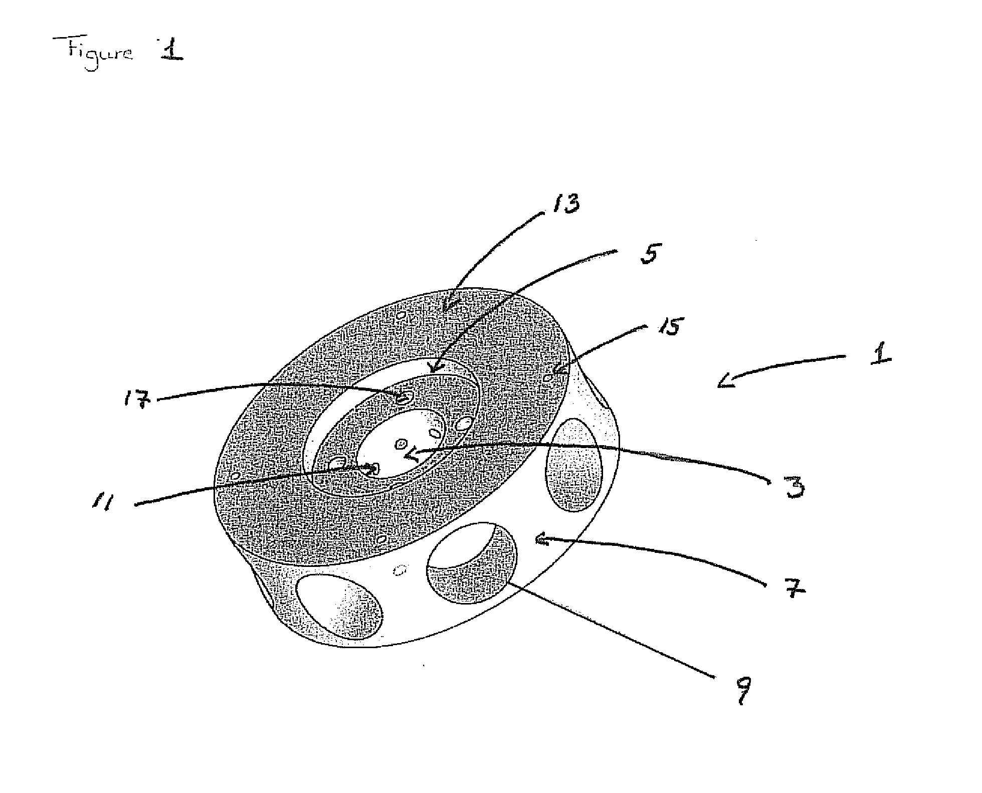
[0016]This invention addresses these problems by providing a device for biological purposes such as cell culturing, enzymatic reactions or filtering of fluid where the device comprises[0017]a body having a first and a second surface defining a body thickness there between, and where said body is delimited by a rim;[0018]an aperture in the centre of the body; said aperture is covered at the first and second surface by a first and second plate, where the first and / or second plate comprises an inlet orifice allowing liquid medium into the aperture;[0019]means for rotating; said means for rotating is arranged in the aperture between the first and second plate[0020]said rim comprises at least one recessed portion for cell culturing; said recessed portion is a cavity in the rim of the body comprising a first outlet orifice allowing the liquid medium to flow out of the body; and a first wall delimiting said recessed portion along said cavity;[0021]at least one outlet channel connecting the...


PUM

PropertyMeasurementUnit
porosityaaaaaaaaaa
thicknessaaaaaaaaaa
conical shapeaaaaaaaaaa

Abstract

A device for biological purposes such as cell culturing, enzymatic reactions or filtering of fluid has a body with first and second surfaces. The body is delimited by a rim and an aperture in the center of the body. The aperture is covered at the first and second surface by first and second plates. The first and / or second plate has an inlet orifice allowing liquid medium into the aperture. Rotating means are arranged in the aperture between the first and second plate. At least one recessed portion is a cavity in the rim of the body having a first outlet orifice allowing the liquid medium to flow out of the body. At least one outlet channel connects the circular aperture with the recessed portion. Liquid is pumped into the aperture of the device and pumped through at least one outlet channel.

Description

FIELD OF THE INVENTION[0001]The present invention relates to a device for obtaining a perfusion flow e.g. for culturing of cells, especially, the culturing of cells in three-dimensional structures. Furthermore, a method for culturing cells and in particular culturing cells in three-dimensional structures is provided. This invention also relates to the use of a device for culturing of cells for the purpose of tissue engineering and artificial organs.BACKGROUND OF THE INVENTION[0002]The culturing of cells is a highly complex matter as different cell types demand different types of liquid medium as well as different growth conditions in order to obtain optimal growth of the cells. The growth conditions include chemical composition and flow rate of the medium, mechanical stimulation, and electromagnetic stimulation.[0003]Cells can be cultured in 2D (dimensional) layers and have traditionally been cultured in culture tissue flasks and culture plates. In this manner, the cells are grown i...

Claims


Application Information

Patent Timeline
Patent Type & Authority Applications(United States)
IPC IPC(8): C12M3/00B01D35/00C12M1/40C12N5/071C12P1/00
CPCC12M27/10C12M29/10C12M27/02B01F13/0827C12M27/00B01F13/08B01F33/45B01F33/453
Inventor LE, DANG QUANG SVENDNYGAARD, JENS VINGEFOSS, MORTENBESENBACHER, FLEMMINGBUNGER, CODY
Owner CAROUCELL APS
Why Eureka
Try Eureka