
Non-Structural Insulating Panel System

a non-structural, panel technology, applied in the direction of heat-insulating, roof drainage, building repairs, etc., can solve the problems of affecting the performance of the system, so as to reduce the cost and the amount of materials required, reduce the cost and the effect of material requirements

Active Publication Date: 2012-07-12
HARDING PETER W
View PDF8 Cites 46 Cited by
  • Summary
  • Abstract
  • Description
  • Claims
  • Application Information

AI Technical Summary

Benefits of technology

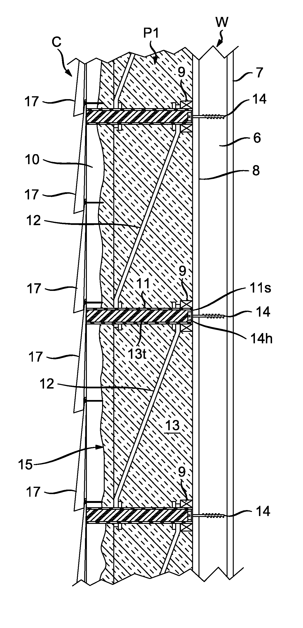
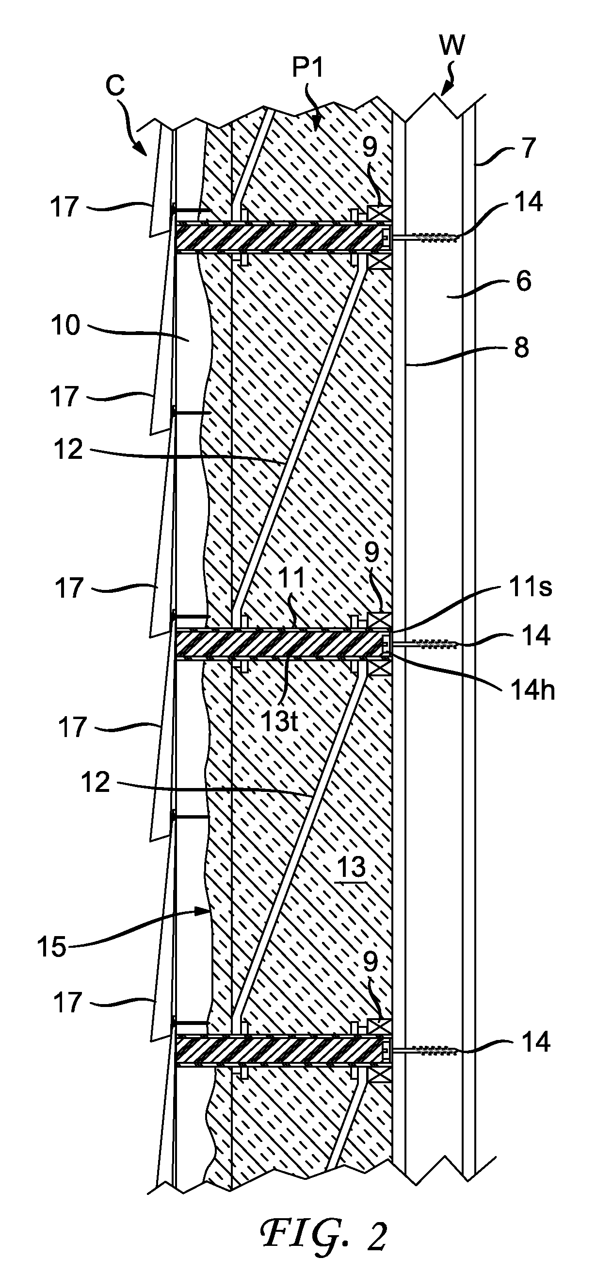
[0024]In a preferred embodiment of the invention, the panel structure has horizontal internal stringers along the inner surface of the panel, the external stringers are vertical, the perpendicularly extending connectors are tubular and extend between the internal and external stringers, and the lateral connectors are shear transfer strips attached to the perpendicularly extending tubular connectors between the internal and external stringers. The lateral connectors and perpendicularly extending tubular connectors preferably are made from low thermal conductivity materials such as plastic or glass fibers, and are embedded in the insulating foam. Because the only elements bridging the basic panel are the low thermal conductivity perpendicular and lateral connectors and foam, the panel may obtain a high degree of thermal resistance.
[0036]The insulating system may be used on any building type in which a structural framework is covered by a weatherproof cladding material. It is well suited for residential, commercial, institutional and industrial buildings. It may be used to insulate above- and below-grade walls and roofs. It may be used in both new construction and in buildings that are being retrofitted to significantly reduce energy consumption.

Problems solved by technology

This practice also has the effect of creating numerous holes in the air / water barrier, thereby compromising its performance.
Retrofitting cavity insulation in existing frame-and-cladding buildings is difficult and costly, the commonest method being to drill holes in either the interior gypsum-board or exterior sheathing in order to blow fiberglass or cellulose insulation into the framing cavities.
Although cavity insulation reduces the flow of heat through a building assembly such as a wall or roof it suffers from a major weaknessheat flow through the framing members.
This strategy is quite effective although expensive due to the material and labor cost of installing the interior framed wall.
Although SIPs provide effective insulation and air-sealing they have found limited acceptance due to their cost, installation difficulties and the difficulties of installing electrical outlets and other services without compromising the structural and thermal integrity of the panels.
These limitations may necessitate installing a non-structural wall against the interior side of the panel with significant additional material and labor cost or providing surface mounted raceways for electrical circuits that compromise the finished appearance of the wall.
Although rigid expanded foam boards potentially provide high thermal insulation and air-sealing the system has significant limitations, principally related to the application of cladding material to the exterior of the foam board.
This approach however can only be used with foam board up to a limited thickness depending on the weight of the cladding material, and for this reason 2″ foam board is the maximum that vinyl siding manufacturers will allow while the manufacturers of fiber cement siding allow a maximum foam thickness of 1.5″.
Other drawbacks to this approach are the large number of small thermal bridges where highly conductive steel nails penetrate through the insulation and the sheathing into the framing and the large number of nail holes in the air / water barrier and insulation board that potentially compromise performance.
Although effective this method of using thick layers of insulating board covered by furring strips is rarely used because of the high cost of the long screws required and the amount of skilled labor time required to correctly install the furring strips.
This method is rarely used in new construction due to its cost and complexity but is sometimes used to significantly increase wall insulation levels in existing construction.
Both methods can be used to create thick walls with very high insulating values but are both materials and labor intensive and therefore costly.
Ojala's panels result in a heavy construction and have a high level of thermal bridging through the web trusses.
Thermal bridging through the reinforcing strips remains a problem.

Method used


Image

  • Non-Structural Insulating Panel System
  • Non-Structural Insulating Panel System
  • Non-Structural Insulating Panel System

Examples


Embodiment Construction

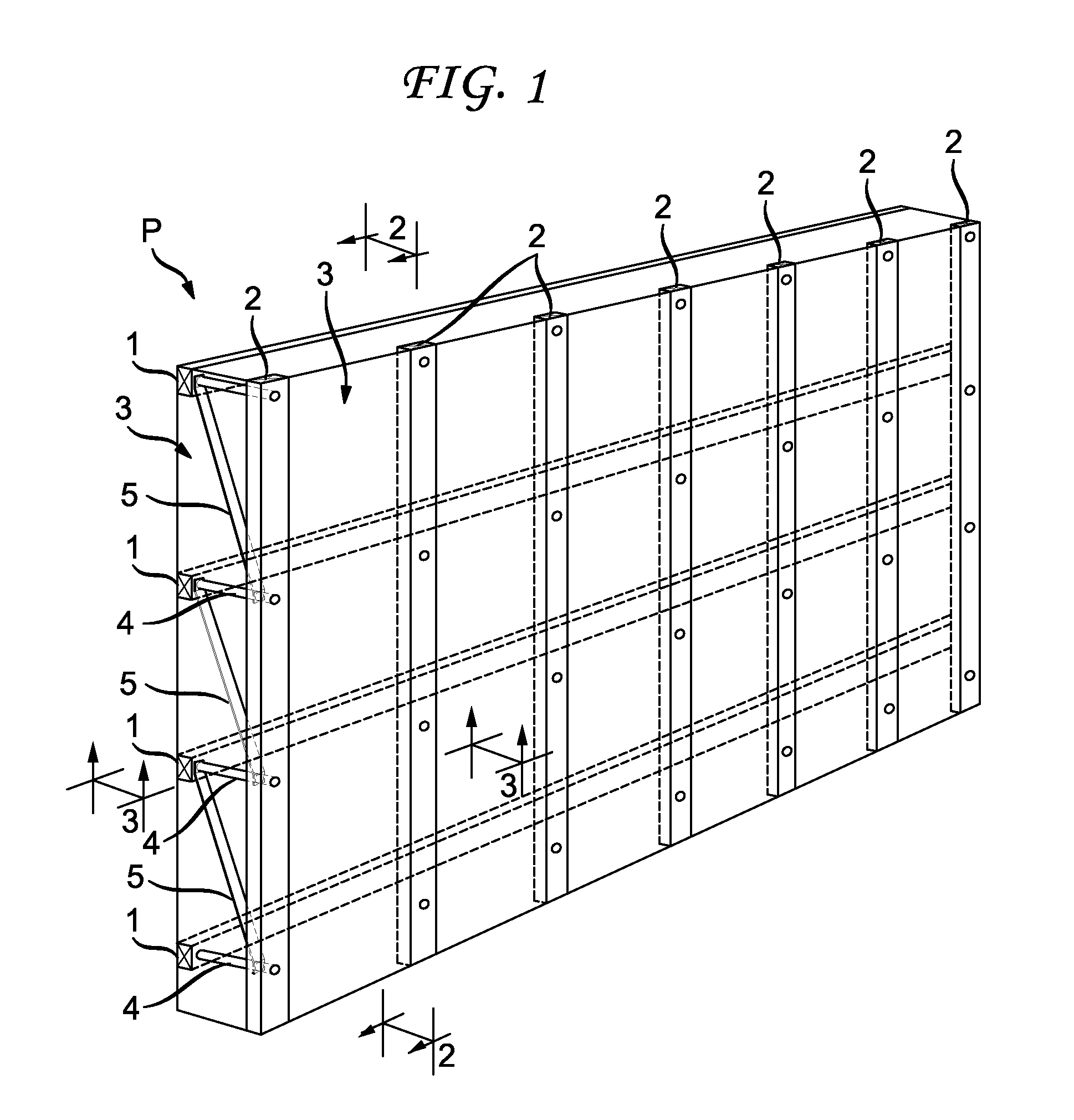
[0053]FIG. 1 is a perspective drawing showing the major components of an insulating panel P according to the invention. The panel P includes a plurality of horizontal stringers 1 at the interior of panel P (located adjacent a building structural wall, not shown) and a plurality of vertical stringers 2 at the exterior of panel P (located adjacent cladding material, not shown). The stringers 1 and 2 are embedded in insulating foam 3. The interior stringers 1 are connected to the exterior stringers 2 at multiple points using perpendicularly extending compression tube spacers 4 and laterally extending connectors or tension strips 5.

[0054]As will be explained below, the panel P is fastened to a building structural wall by means of and at the locations of the compression tubes 4. The laterally extending connectors or tension strips 5 connect the inner end of one compression tube 4 with the outer end of the compression tube in the row below. Accordingly, a compression tube 4, a lateral ten...


PUM


Abstract

An insulating panel structure for application to the exterior of a building, the panel structure having an inner surface to be attached to the building and an outer surface to be attached to an exterior load such as cladding material. The panel structure has external stringers along the outer surface of the panel for attachment of the exterior load, connectors extending perpendicularly from the internal surface to the external stringers to transmit compressive forces from the exterior load to the building, lateral connectors that run diagonally upward from the external stringers to the inner surface to transmit tensile forces from the weight of the exterior load from the external stringers of the panel to the building, and insulating foam embedded in the space defined between the inner and outer surfaces. A method of panel manufacture includes construction at a manufacturing site with incorporation of elements into panels such as doors, windows, gutters and downspouts, transporting the assembled panel to a job site, and attaching it to a building. An apparatus and method for transporting insulating panels includes providing panels with tubular connectors extending into the panels from their outer surfaces, and providing expansible fingers insertable into the tubular connectors and mounted on a movable frame, inserting the fingers into the connector tubes, expanding them to grip the tubes and panels, moving the frame with expanded fingers and panel to a job site, attaching the panel to a building while being held with the expanded fingers, and contracting the fingers to retract the fingers and frame from the attached panel.

Description

CROSS-REFERENCE TO RELATED APPLICATION[0001]This application claims the benefit of the filing date of Provisional Application No. 61 / 399,480, filed Jul. 13, 2010.FIELD OF THE INVENTION[0002]This invention relates to systems and structures for insulating the walls and roofs of buildings.BACKGROUND OF THE INVENTION[0003]Energy consumption in residential and commercial buildings is estimated to account for 21% and 18% respectively of primary energy consumption in the USA. Given the projected decline in the production of fossil fuels and the growth in global demand for energy it is recognized in both the public and private sectors that reducing energy consumption in residential and commercial buildings is an international imperative.[0004]The commonest construction system used in the USA and in many other countries in both the residential and the commercial sectors is a structural frame that is covered by a weatherproof cladding. The structural frame is designed to withstand all the loa...

Claims


Application Information

Patent Timeline
IPC IPC(8): E04B2/06E04G21/16B66C1/54E04B1/74E04B1/64
CPCB66F9/142Y02B30/94E04C2/00E04F13/0885E04B7/22E04D13/064E04D13/0645E04D13/076E04D13/08E04D13/158E04D2013/045E04D2013/0806E04G21/167E04B1/762B66F9/185Y02A30/00Y02B30/90E04B1/7629E04B1/7675E04B1/80E04C2/46E04F21/18
Inventor HARDING, PETER W.
Owner HARDING PETER W
Learn More