
Method for attaching labels to items

Inactive Publication Date: 2012-07-12
UPM RAFLATEC OY
View PDF8 Cites 6 Cited by
  • Summary
  • Abstract
  • Description
  • Claims
  • Application Information

AI Technical Summary

Benefits of technology

[0014]Thanks to the invention, a higher fraction of the optical power may be utilized for heating the bonding layer. Energy consumption of the process may be reduced.
[0016]In an embodiment, a high energy density may be used for heating a thermally activatable adhesive of the bonding layer. Consequently, the total time needed for heating the label may be reduced. Thus, the overall energy consumption may be reduced, and / or the speed of attaching the labels to products may be increased.
[0017]In an embodiment, the thickness of the carrier layer may be reduced and / or the carrier layer may be made of a material which has a lower softening temperature. Thus, the overall energy consumption may be reduced, and / or less materials may be consumed when producing the labels. Consequently, the production method of the labels may be more economical and / or environmentally friendly.
[0018]The use of a release liner may be avoided. Consequently, the amount of waste material may be reduced.
[0021]In an embodiment, the label does not need to completely surround an item. This is an improvement over known shrink-sleeve labels where heat is used for shrinking the label material.

Problems solved by technology

They suffer however from a number of disadvantages which include the fact that the production process is rather complex and in some cases waste material unnecessarily burdening the environment is created.
At this phase the release liner becomes a waste product which is a major disposal issue for users of such labels and the industry at large as well as the whole environment.
Typically, such wet-glue label operations are rather messy with a large amount of time being lost for clean-up, set-up and changing of label formats.
In addition such wet-glue labels almost always exhibit the unsightly gripper marks of the “label-box” on the finished labelled object.
Furthermore wet-glue labels are not available with clear films due to the technical problem that the water cannot satisfactorily evaporate and escape from below the labels, always resulting in unsightly bubbles in the label.
Another decoration technology is that of shrink-sleeves, in which case the total applied cost is very high and the production process very complex.
Shrink-sleeve films are normally printed on wide-web gravure or flexographic presses based on such inks, which could cause environmental and safety hazards.
These include the fact that by definition a shrink-sleeve covers the whole surface of the object to be labelled and therefore 180° decoration or a label covering only part of the container surface is not possible.
The visibility of unsightly seams on shrink-sleeve labels is also negative issue.
It is not in practice possible to use shrink-sleeves for containers with flat sides or with containers with handles.
Further, it is not possible to use paper labels with shrink-sleeves nor is it possible to have a variety of textures or tactile effects.
It is also not possible to have spot labels, multiple labels on a container or unique label shapes when using shrink-sleeves.
It is also not possible to achieve the so-called “No-label” look with shrink-sleeves, that is, it is not possible to have the label blend into the container colour and material as if the label was not there and that the container was pre-printed.
The major markets for such labels are soft drinks and mineral waters due to the lack of premium look and therefore marketing appeal of the labels.
It is not possible in this case to achieve the “No-label” look.
The choice of materials is very limited and design variety is restricted to that of simple cylindrical shapes.

Method used


Image

  • Method for attaching labels to items
  • Method for attaching labels to items
  • Method for attaching labels to items

Examples


example 4

[0196] The method according to any of the examples 1 to 3 wherein the carrier layer (10) is paper.

[0197]Example 5. The method according to any of the examples 1 to 3 wherein the carrier layer (10) is plastic.

[0198]Example 6. The method of example 5 wherein the carrier layer (10) is transparent in the visible region (VIS) of light.

[0199]Example 7. The method according to any of the examples 1 to 6 wherein the bonding layer (20) comprises an acrylic adhesive, which is in a non-tacky state prior to said heating.

[0200]Example 8. The method according to any of the examples 1 to 6 wherein the bonding layer (20) comprises a polyurethane adhesive, which is in a non-tacky state prior to said heating.

[0201]Example 9. The method according to any of the examples 1 to 8 wherein the bonding layer (20) comprises a dye, which absorbs infrared light (IR1).

[0202]Example 10. The method of example 9 wherein the infrared light (IR1) is provided by a tungsten halogen lamp (200),

[0203]Example 11. The meth...

example 17

[0209] The method according to any of the examples 1 to 16 wherein the bonding layer (20) comprises a light-scattering filler material.


PUM

PropertyMeasurementUnit
Temperatureaaaaaaaaaa
Fractionaaaaaaaaaa

Abstract

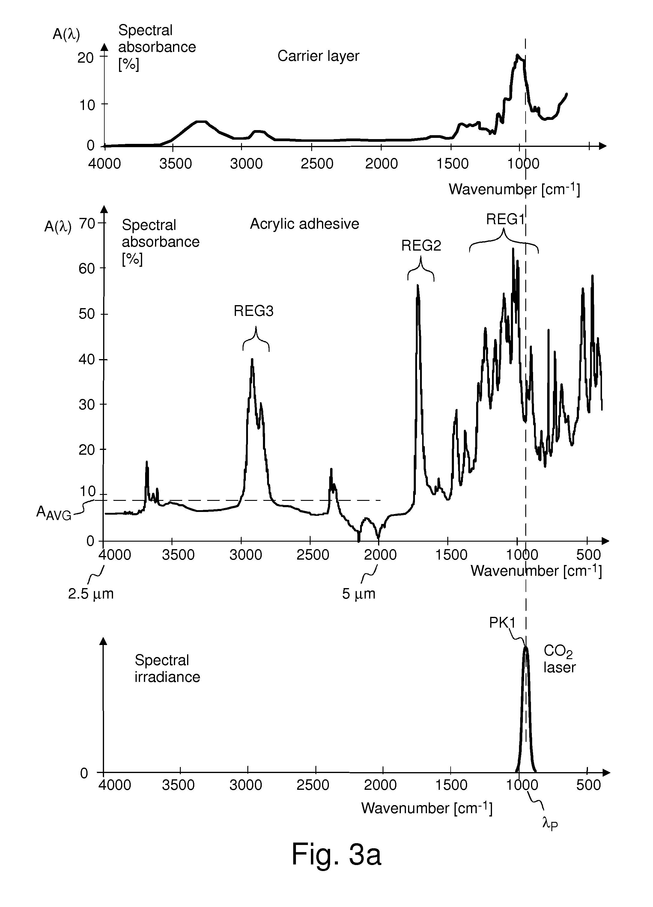
A method for attaching a label to a surface of an item. The label includes a carrier layer and a bonding layer. The method includes heating the bonding layer using infrared light such that the infrared light has a maximum spectral irradiance at a peak wavelength. The bonding layer has an absorbing spectral region that spectrally matches with the peak wavelength.

Description

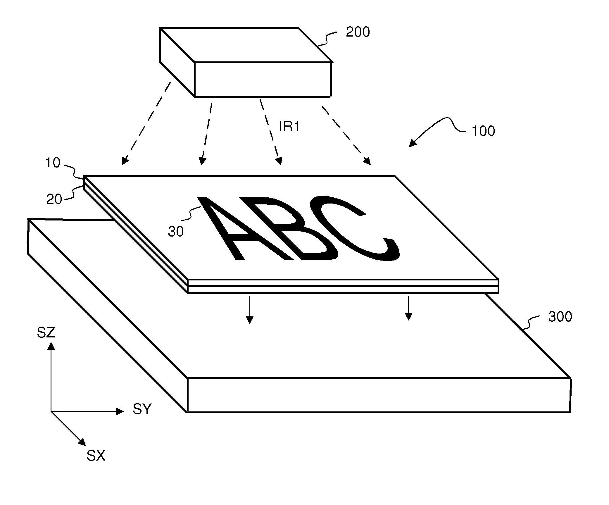
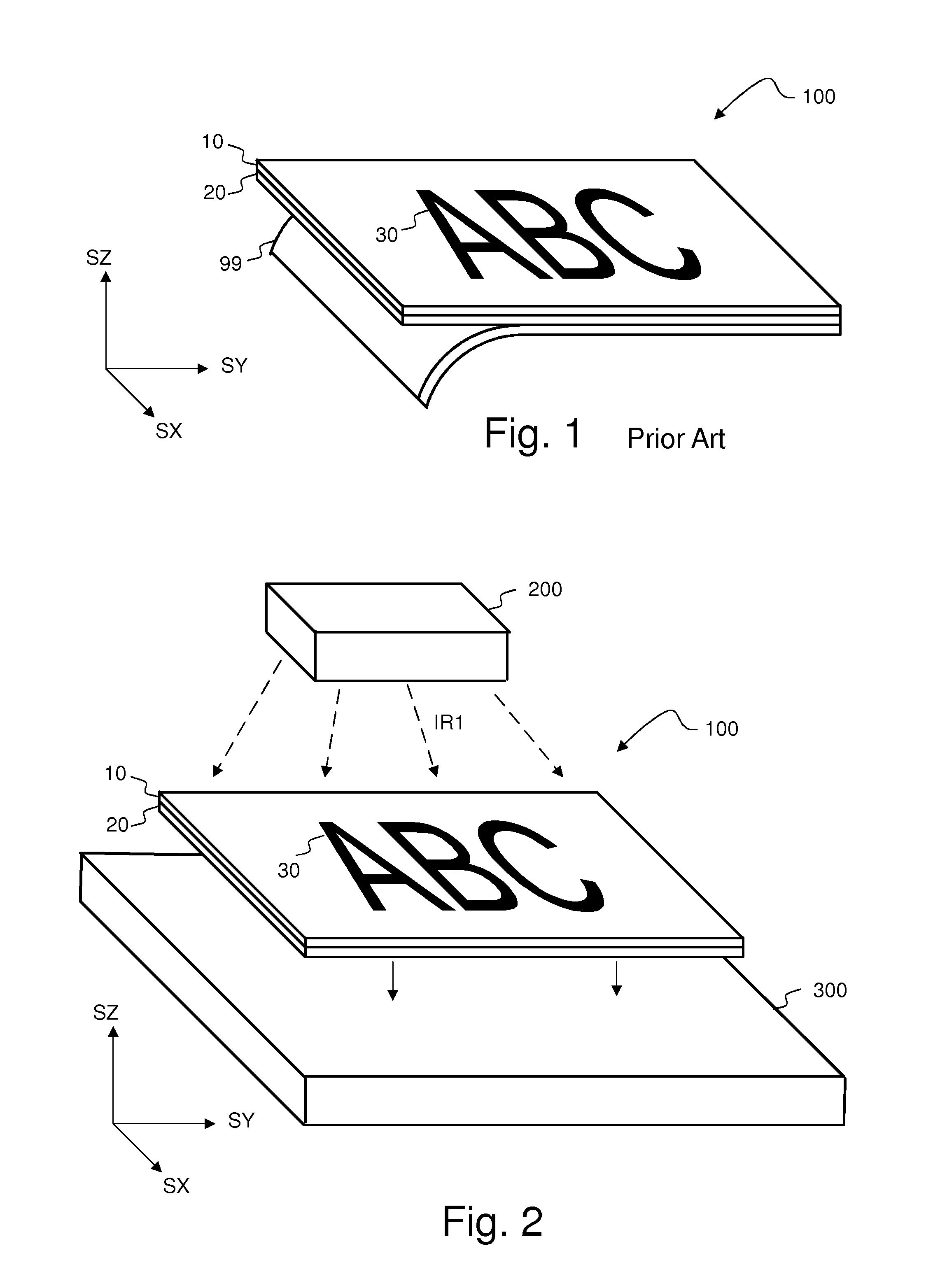
FIELD OF THE INVENTION[0001]The present invention relates to a method for attaching labels to items.BACKGROUND OF THE INVENTION[0002]Labels may be attached to items e.g. in order to visually show information associated with the item. The information may comprise e.g. trademark of a manufacturer, advertising information, price information, or operating instructions.[0003]There are a number of label decoration technologies available, each possessing various advantages and challenges. Self-adhesive or pressure-sensitive labels are well-known and widely used in the industry. They suffer however from a number of disadvantages which include the fact that the production process is rather complex and in some cases waste material unnecessarily burdening the environment is created.[0004]Referring to FIG. 1, a known label 100 comprises a carrier layer 10, an adhesive layer 20, and a removable release liner 99. The carrier layer 10 may comprise printed patterns 30.[0005]Traditionally, a release...

Claims


Application Information

Patent Timeline
IPC IPC(8): B29C65/14C09J7/21C09J7/22C09J7/35
CPCG09F3/10G09F2003/025G09F2003/0273B65C9/25C09J5/06C09J7/0242C08K5/0041C09J2203/334C09J2205/102C09J2205/31C09J2433/00C09J2475/00C09J2400/283C09J7/043C09J7/35C09J7/22C09J7/21C09J2301/416C09J2301/408
Inventor METSAJOKI, KATIMITCHELL, NOEL
Owner UPM RAFLATEC OY
Learn More