Dual Load Path Design for a Vehicle

a dual-load path and vehicle technology, applied in the direction of roofs, bumpers, battery/fuel cell control arrangements, etc., can solve the problem of using other energy-absorbing structures

Active Publication Date: 2012-07-12
TESLA INC
View PDF6 Cites 24 Cited by
  • Summary
  • Abstract
  • Description
  • Claims
  • Application Information

AI Technical Summary

Problems solved by technology

While crash energy may be absorbed in the bumper, large impact cras

Method used


Image

  • Dual Load Path Design for a Vehicle
  • Dual Load Path Design for a Vehicle
  • Dual Load Path Design for a Vehicle

Examples


Embodiment Construction

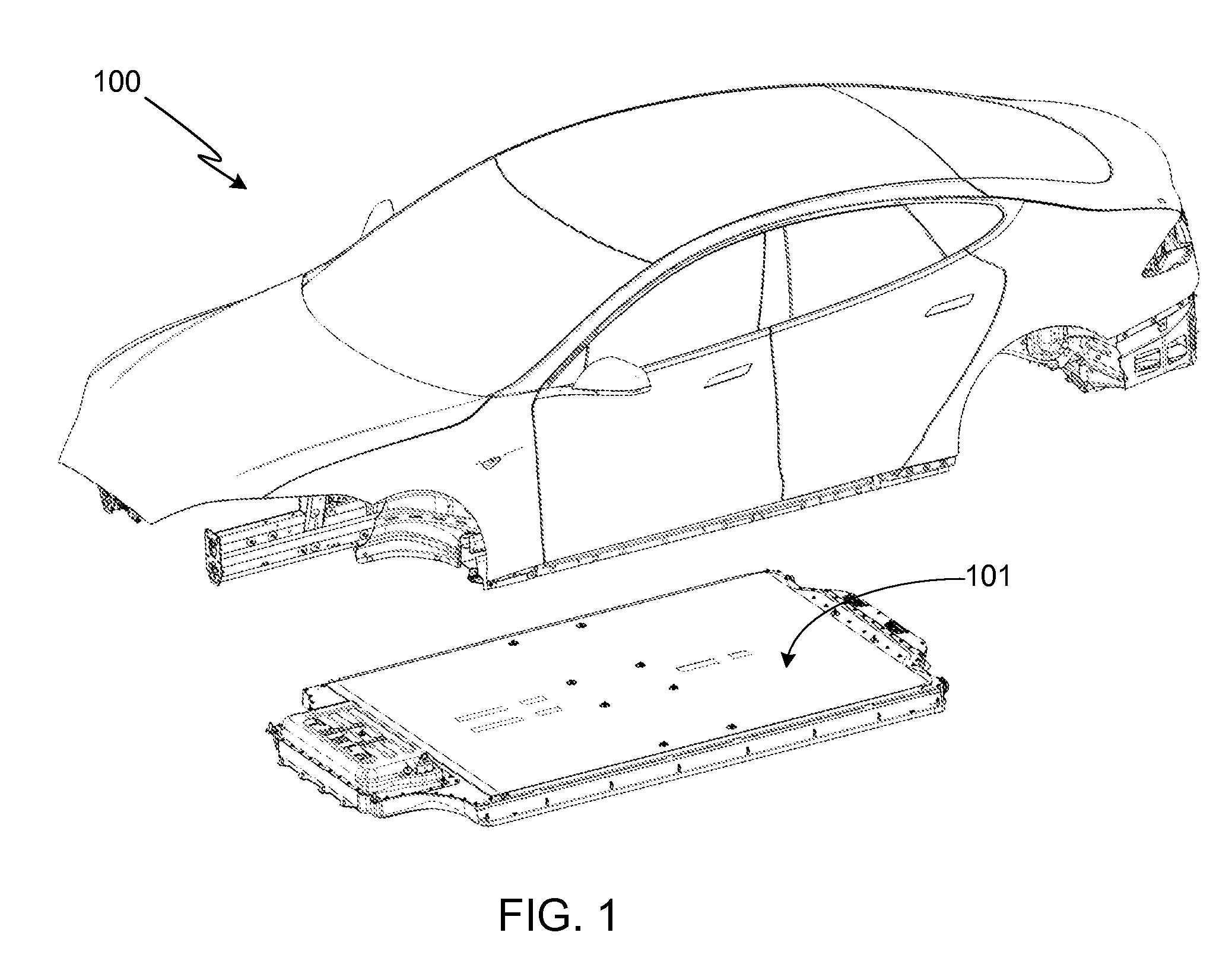
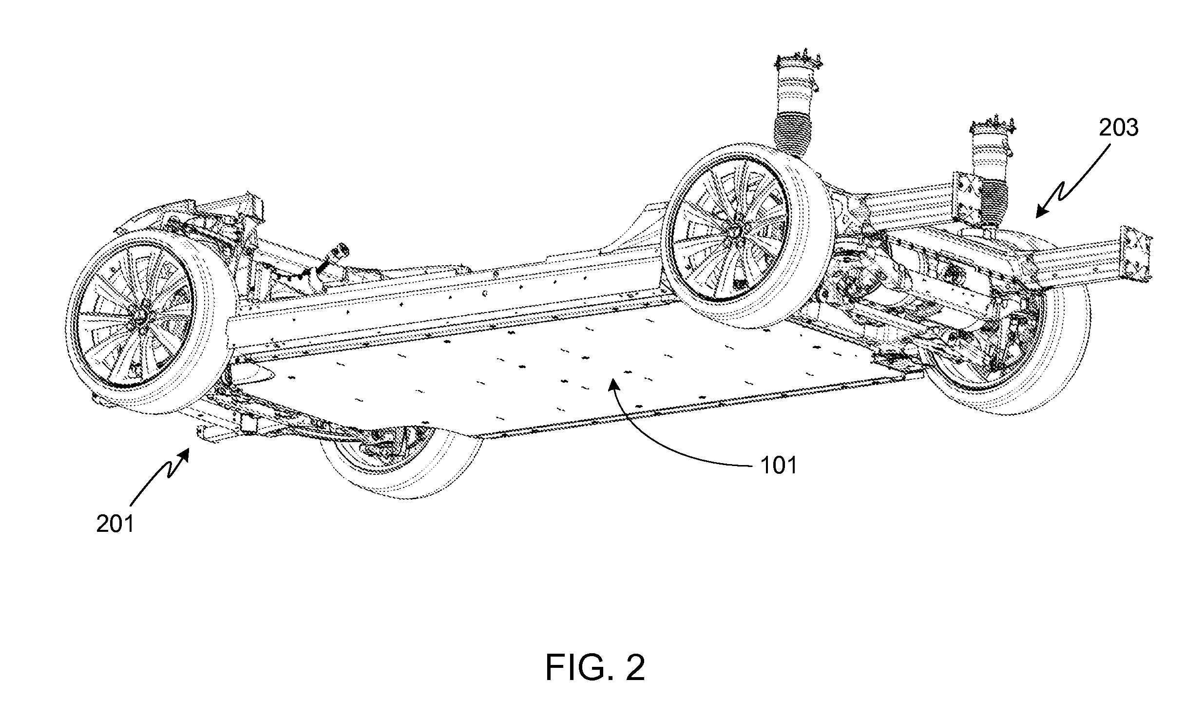
[0040]In the following text, the terms “battery”, “cell”, and “battery cell” may be used interchangeably and may refer to any of a variety of different cell types, chemistries and configurations including, but not limited to, lithium ion (e.g., lithium iron phosphate, lithium cobalt oxide, other lithium metal oxides, etc.), lithium ion polymer, nickel metal hydride, nickel cadmium, nickel hydrogen, nickel zinc, silver zinc, or other battery type / configuration. The term “battery pack” as used herein refers to multiple individual batteries electrically interconnected to achieve the desired voltage and capacity for a particular application. The batteries of the battery pack are contained within a single piece or multi-piece housing referred to herein as a battery pack enclosure, and often referred to herein as simply the “battery pack”. The term “electric vehicle” as used herein refers to either an all-electric vehicle, also referred to as an EV, a plug-in hybrid vehicles, also referre...


PUM


Abstract

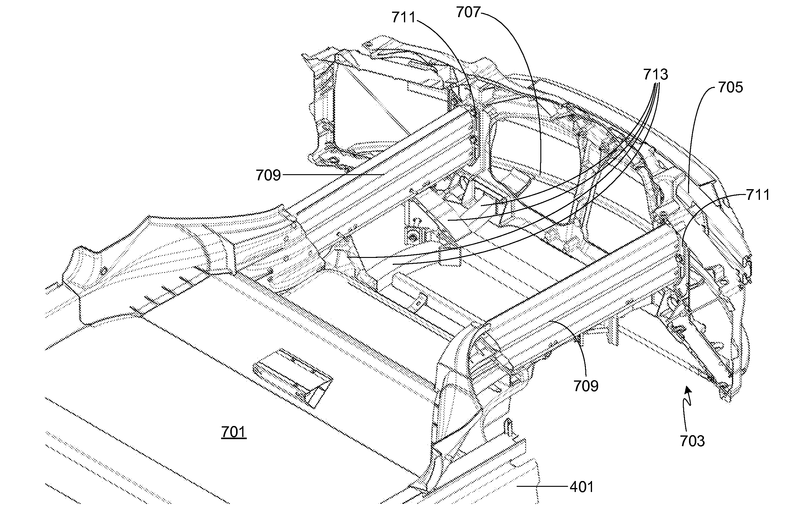
A system for absorbing and distributing front impact forces in a vehicle is provided, the system including a primary impact system and a secondary impact system, each of which includes a bumper and a structure for transferring impact loads. The primary impact system includes a primary bumper and a pair of front rails spaced apart in a widthwise direction with each rail extending lengthwise, where one end portion of each rail is mechanically coupled to the vehicle's bumper and the other end portion of each rail is mechanically coupled to a torque box. The secondary impact system includes a secondary bumper and an assembly of sub-frame components separate from the front rails that allow impact loads to be transferred in parallel through the front rails and the sub-frame.

Description

CROSS-REFERENCE TO RELATED APPLICATION[0001]The present application claims is a continuation of U.S. patent application Ser. No. 13 / 337,070, filed 24 Dec. 2011, and claims benefit of the filing date of U.S. Provisional Patent Application Ser. No. 61 / 430,622, filed 7 Jan. 2011, the disclosure of which is incorporated herein by reference for any and all purposes.FIELD OF THE INVENTION[0002]The present invention relates generally to vehicle structures and, more particularly, to front-end vehicle structures that provide enhanced load distribution and occupant safety.BACKGROUND OF THE INVENTION[0003]Modern vehicles use a variety of structures to protect the vehicle's occupants during a crash. Some of these structures are used to control the transmission of the crash energy to the passenger compartment while other structures, such as seat belts, head restraints, and air bags, are intended to restrain passenger movement during a crash, thereby preventing the passengers from hurting themsel...

Claims


Application Information

Patent Timeline
IPC IPC(8): B60R19/26
CPCB60K1/04B60K2001/0438B60R19/34B62D25/2018B62D25/082B62D25/20B62D21/152B60L50/64B60L50/66B60L53/80B60L58/21Y02T10/70Y02T10/7072
Inventor RAWLINSON, PETER DORE
Owner TESLA INC
Why Eureka
Try Eureka