Wireless MEMS sensor and method of reading the same

a technology of wireless sensors and sensors, applied in the direction of optical radiation measurement, instruments, wireless architecture usage, etc., can solve the problems of limited electrical quality factor, high cost of manufacturing, and high cost of tangents of mems resonators, etc., to achieve high frequency, low manufacturing cost, and long reading distance

Inactive Publication Date: 2012-07-12
TEKNOLOGIAN TUTKIMUSKESKUS VTT
View PDF6 Cites 11 Cited by
  • Summary
  • Abstract
  • Description
  • Claims
  • Application Information

AI Technical Summary

Benefits of technology

[0014]According to an embodiment, a passive wireless sensor or tag can be realized with the well-established MEMS technology. This wireless MEMS sensor enables very-low manufacturing costs, long reading distance, high frequencies, and compact tag size. In addition, the wireless sensors can be passive requiring no embedded electronics.
[0015]According to an embodiment, the wireless sensor, when illuminated at two harmonic frequencies, produces an intermodulation frequency, which is emitted to the reader. The interrogation method of the proposed sensor is somewhat similar to the harmonic radar concept, which was first proposed for traffic applications [5] and later was used for tracking insects [6]-[8]. However, as compared to the harmonic radar, the proposed method enables a smaller frequency offset between the transmitted and received signals which eases to fulfill the frequency regulations and facilitates circuit design. The interrogation method is proposed, for example, for automotive radars to detect pedestrians, bicyclists, and other road users who are high risk to serious injury in traffic accidents [9].

Problems solved by technology

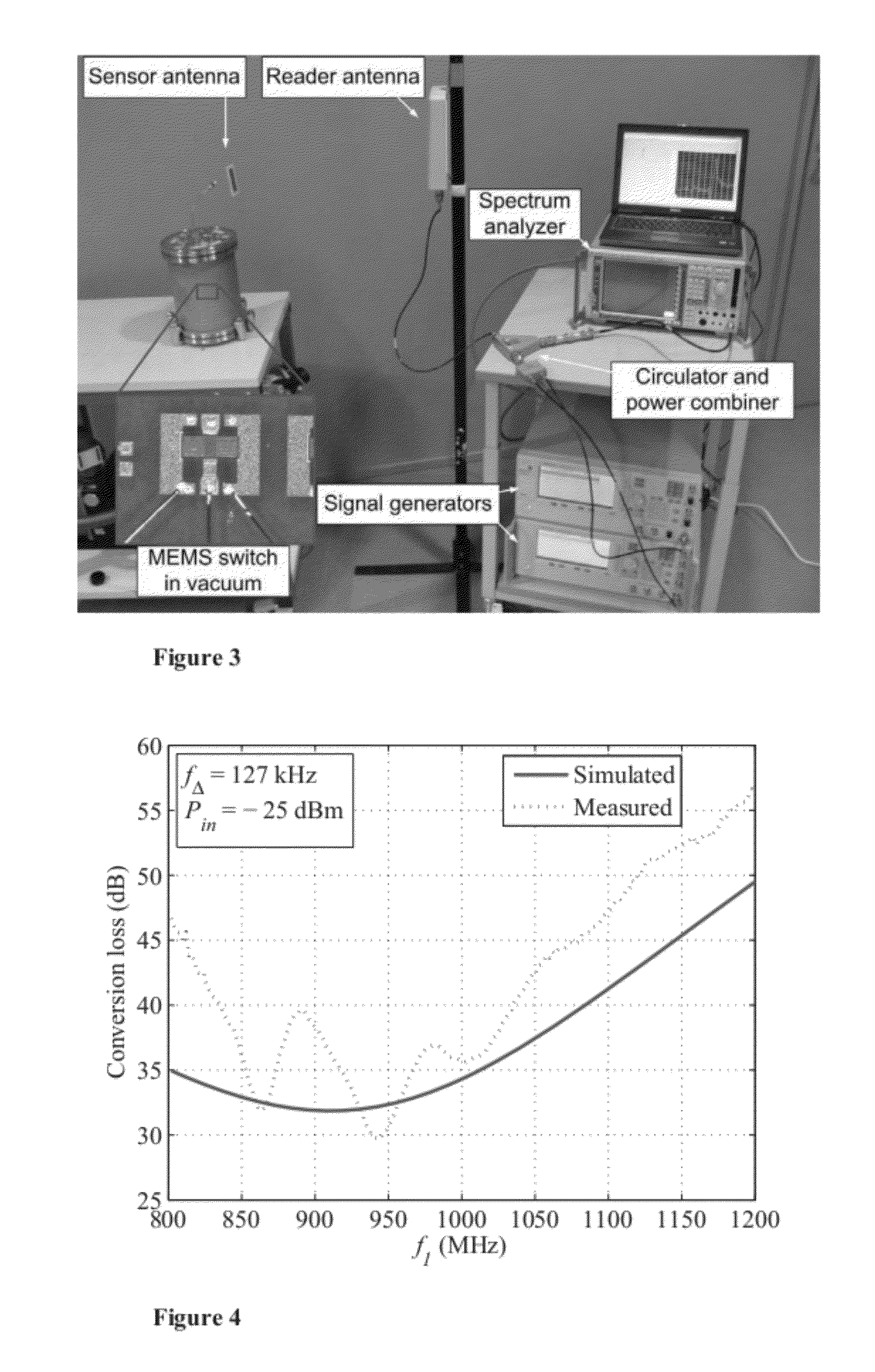
The electrical quality factor is limited either by the conductor losses or by the equivalent electrical resistance of the MEMS resonator.
Therefore, this analysis underestimates the equivalent resistance.
However, (13) shows that the loss tangent of the MEMS resonator is typically very low at low input power levels, and therefore the loss tangent of a practical system is dominated by conductor losses.
Note that the experimental device may suffer from impedance mismatch between the generator and the MEMS, which is included into electrical quality factor in the fitting process.
Similarly, friction of the unpacked cantilever structure is related to the mechanical quality factor and is sensitive to air pressure and humidity.

Method used


Image

  • Wireless MEMS sensor and method of reading the same
  • Wireless MEMS sensor and method of reading the same
  • Wireless MEMS sensor and method of reading the same

Examples


Embodiment Construction

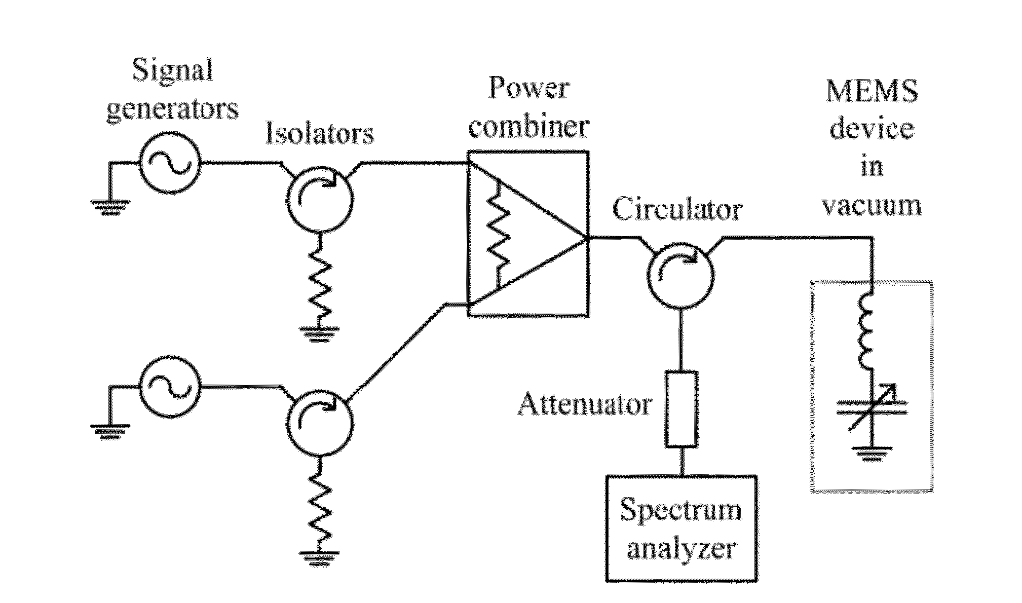
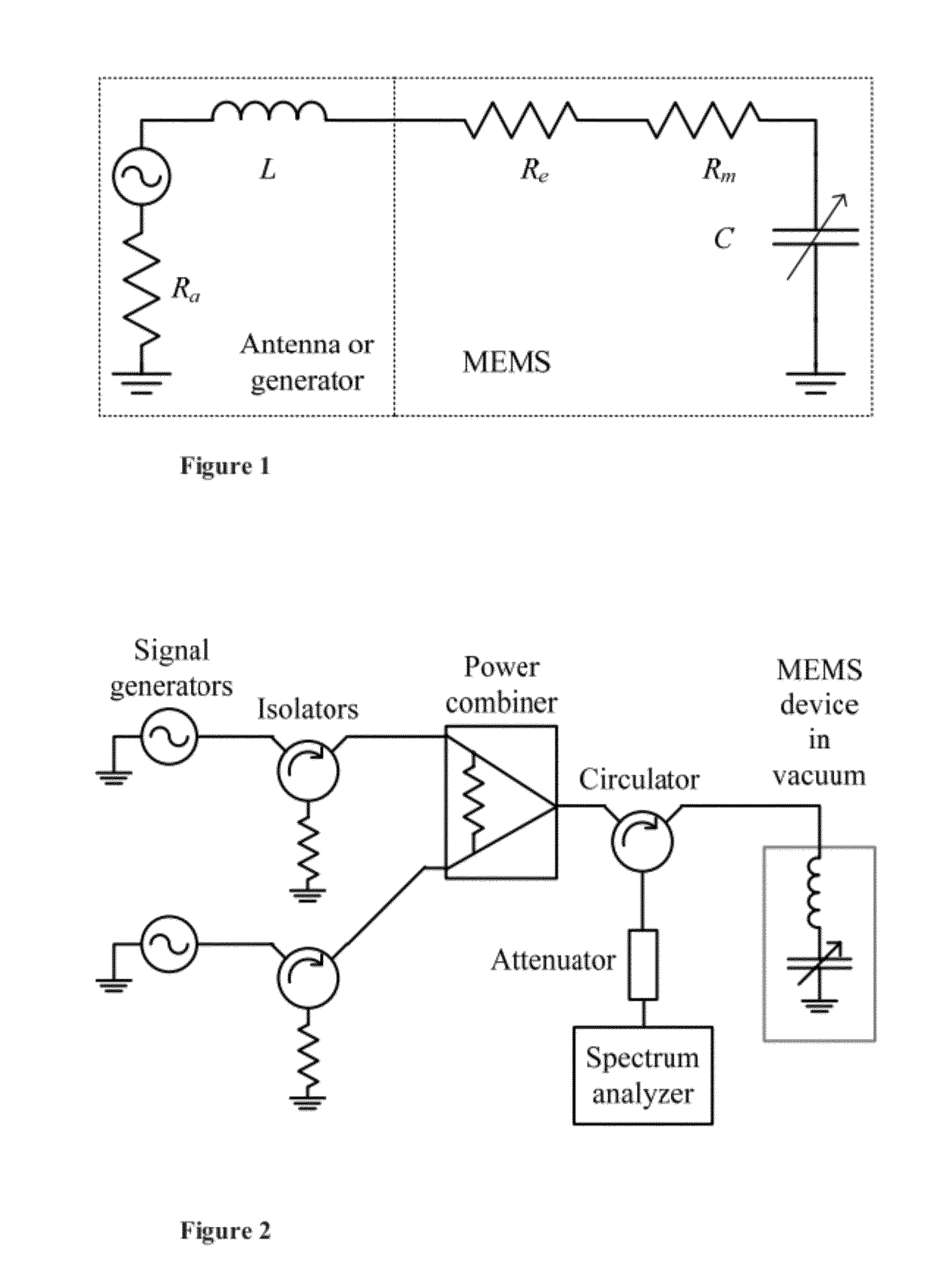
[0033]According to an embodiment, the wireless sensor comprised a MEMS resonator and an antenna directly matched thereto.

[0034]The wireless sensor can be comprised in a single silicon chip.

[0035]In an embodiment, the sensor is a passive sensor and the single silicon chip does not include a power rectifier nor a power source.

[0036]The wireless sensor can also comprise a logic circuit.

[0037]In an embodiment, the wireless sensor comprises a logic implemented by a CMOS circuit manufacture on a single silicon chip together with the MEMS resonator and the antenna.

[0038]The MEMS resonator of the wireless sensor typically has three MEMS parameters: the mechanical quality factor, the mechanical resonance frequency, and the electrical resonance frequency. In an embodiment, at least one of the three parameters is made sensitive to the measured quantity. The measured quantity itself can be temperature, strain, air pressure or humidity, for instance.

[0039]In an embodiment, the wireless sensor is...


PUM


Abstract

This document describes a wireless sensor comprising a MEMS resonator and an antenna directly matched thereto. Also a method of reading the wireless sensor is described. The method comprises illuminating the wireless sensor with electromagnetic energy at a first and second frequencies and receiving an intermodulation signal emitted by the wireless sensor in response to said electromagnetic energy at the first and second frequencies.

Description

TECHNICAL FIELD[0001]The present invention relates generally to wireless sensors and methods of reading the wireless sensors.[0002]In particular, the wireless sensor is of the type utilizing MEMS technology (Micro-Electro-Mechanical Systems).BACKGROUND ART[0003]Wireless sensors have a great deal of potential in numerous applications that are too expensive or impossible to monitor by wire. Wireless sensors are divided into battery-powered active devices containing a radio transmitter, semi-passive battery-assisted sensors using modulated backscattering technique, and fully passive sensors. The disadvantages of active sensors are their high cost and limitations due to the battery's lifetime. Existing passive and semi-passive wireless sensors are based either on silicon-based radio frequency identification (RFID) or surface acoustic wave (SAW) technology.[0004]Advanced RFID technology enables low-cost passive and semi-passive tags (i.e., ID-sensors) with rewritable memory. The technolo...

Claims


Application Information

Patent Timeline
Patent Type & Authority Applications(United States)
IPC IPC(8): G01J1/42H01L29/84H01L27/14
CPCG01S13/753G01D21/00H04Q9/00H04Q2209/47G01L9/0008G01L19/00
Inventor SEPPA, HEIKKIVIIKARI, VILLE
Owner TEKNOLOGIAN TUTKIMUSKESKUS VTT
Why Eureka
Try Eureka