
Secure Data Transmission Using Spatial Multiplexing

a data transmission and spatial multiplexing technology, applied in the field of optical transmission equipment, can solve the problems of small extra loss, single-mode and conventional multi-mode fibers are inherently vulnerable to bend-induced tapping, and both such systems are vulnerable to tapping

Inactive Publication Date: 2012-07-12
ALCATEL LUCENT SAS
View PDF7 Cites 42 Cited by
  • Summary
  • Abstract
  • Description
  • Claims
  • Application Information

AI Technical Summary

Benefits of technology

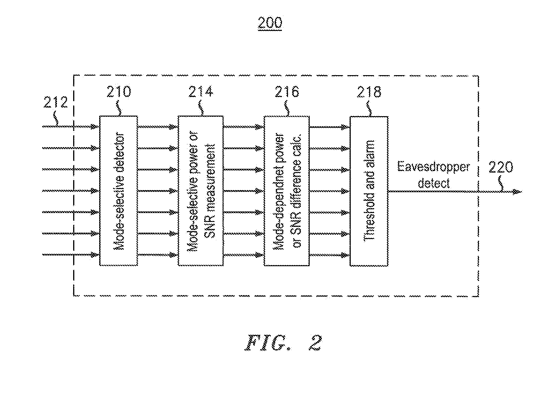
[0008]The systems described above in the Background of the Specification have at least two important detriments. First, single-mode and conventional multi-mode fibers are inherently vulnerable to bend-induced tapping. Second, a system using in-line optical amplifiers will generally equalize the power levels of the amplified signals at all wavelengths and will hence convert a wavelength-dependent loss differential into a signal-to-noise ratio (SNR) differential, which in turn prohibits the detection of an eavesdropper by a simple differential loss measurement at the receiver.
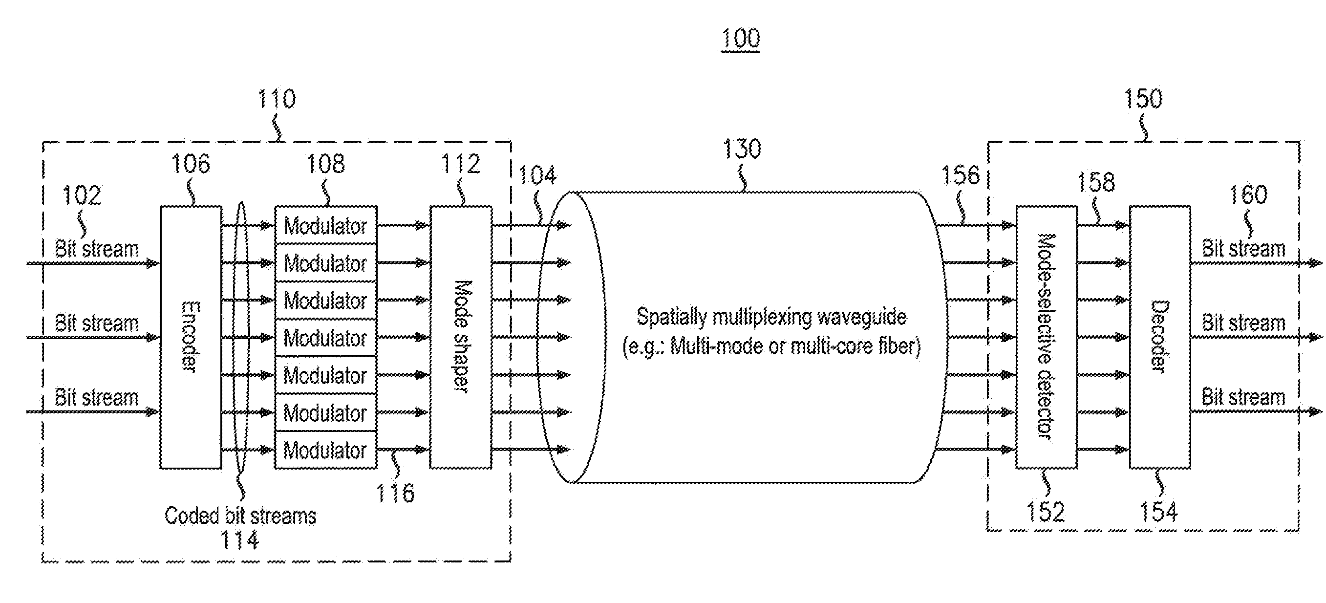
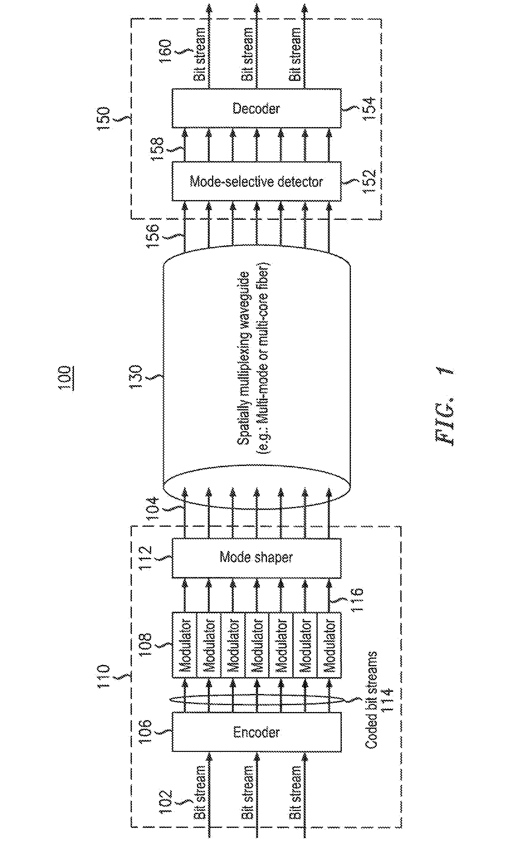
[0010]Embodiments provided herein address one or more of the detriments associated with transmitting data using physical-layer security based on classical optical communications without the need to resort to quantum-cryptographic techniques such as quantum key distribution. One or more embodiments herein disclosed allow for secure physical-layer transmission over spatially multiplexed (e.g., multi-core or multi-mode) optical fiber. One or more disclosed embodiments allow for reception of secure physical-layer transmissions over spatially multiplexed (e.g., multi-core or multi-mode) optical fiber. Still other disclosed embodiments provide the ability to identify the presence of an eavesdropper tapping into such fiber utilized for such spatially multiplexed physical-layer transmission through the use of spatially-resolved differential loss or Signal-To-Noise-Ratio (SNR) measurements.

Problems solved by technology

Both such systems are vulnerable to tapping, which is done by bending the transmission fiber such that a small amount of light is coupled out at a local bend.
The small amount of extra loss is not easily detectable at the rightful receiver located at the end of the transmission fiber, which permits the eavesdropper to go unnoticed.
First, single-mode and conventional multi-mode fibers are inherently vulnerable to bend-induced tapping.
Second, a system using in-line optical amplifiers will generally equalize the power levels of the amplified signals at all wavelengths and will hence convert a wavelength-dependent loss differential into a signal-to-noise ratio (SNR) differential, which in turn prohibits the detection of an eavesdropper by a simple differential loss measurement at the receiver.
Furthermore, while quantum-based techniques to obtain physical-layer security may be fundamentally robust to eavesdropping, they are not compatible with an optically amplified transmission infrastructure, which severely limits their reach as well as their applicability in realistic commercial networks.

Method used


Image

  • Secure Data Transmission Using Spatial Multiplexing
  • Secure Data Transmission Using Spatial Multiplexing
  • Secure Data Transmission Using Spatial Multiplexing

Examples


Embodiment Construction

[0033]Various example embodiments will now be described more fully with reference to the accompanying figures, it being noted that specific structural and functional details disclosed herein are merely representative for purposes of describing example embodiments. Example embodiments may be embodied in many alternate forms and should not be construed as limited to only the embodiments set forth herein.

[0034]It will be understood that, although the terms first, second, etc. may be used herein to describe various elements, these elements should not be limited by these terms since such terms are only used to distinguish one element from another. For example, a first element could be termed a second element, and, similarly, a second element could be termed a first element, without departing from the scope of example embodiments. Moreover, a first element and second element may be implemented by a single element able to provide the necessary functionality of separate first and second ele...


PUM


Abstract

An example transmitter includes an encoder, a plurality of modulators and a spatial multiplexer. The encoder is configured to encode one or more input bit streams into a plurality of coded bit streams which are provided as output. Each modulator is configured to receive and modulate a respective one of the plurality of coded bit streams and to provide a modulated output signal. The spatial multiplexer is configured to spatially multiplex the plurality of modulated output signals for insertion on a spatially multiplexing waveguide. A modulated output signal(s) may be inserted onto a mode of a multi-mode fiber or onto a core of a multi-core fiber. In one embodiment, a subset of the plurality of spatially multiplexed modulated output signals which correspond to the one or more input bit streams must be simultaneously and spatially selectively detected in order to recover a first input bit stream.

Description

PRIORITY CLAIM[0001]The application claims benefit of U.S. Provisional Application No. 61 / 431,040 filed, Jan. 9, 2011.CROSS REFERENCE TO RELATED APPLICATIONS[0002]The subject matter of this application is related to that of U.S. patent application Ser. No. ______, by Peter J. Winzer, attorney docket reference 809508, filed on the same date and the present application, and entitled “SECURE DATA TRANSMISSION USING SPATIAL MULTIPLEXING”, which application is incorporated herein by reference in it entirety.FIELD OF THE INVENTION[0003]The invention relates to optical transmission equipment and, more specifically but not exclusively to the equipment that enables data transmission using spatial multiplexing.BACKGROUND INFORMATION[0004]This section introduces aspects that may help facilitate a better understanding of the disclosed invention(s). Accordingly, the statements of this section are to be read in this light and are not to be understood as admissions about what is in the prior art o...

Claims


Application Information

Patent Timeline
IPC IPC(8): H04L27/00H04J3/00H04J1/00
CPCH04B10/2581H04B10/5053H04B10/5055H04J14/04H04J14/00H04J14/02H04B10/85H04B10/07953H04B10/60H04J14/06
Inventor WINZER, PETER J.
Owner ALCATEL LUCENT SAS
Learn More