Optical device and method for non-invasive real-time testing of blood sugar levels

a real-time testing and optical device technology, applied in the field of optical devices and methods for non-invasive real-time testing of blood sugar levels, can solve the problems of limited shelf life of strips, limited usability, and increased public health problems, and achieve the effects of improving patient safety, increasing the cost of strips, and increasing the number of patients

Inactive Publication Date: 2012-07-12
THE UNIVERSITY OF AKRON
View PDF0 Cites 78 Cited by
  • Summary
  • Abstract
  • Description
  • Claims
  • Application Information

AI Technical Summary

Problems solved by technology

Moreover, obesity is an ever-increasing public health problem.
Moreover, strips are specifically designed for their respective meters, are usable one-time only, and are quite costly.
Strips have a limited shelf life, and the meter will not function if the expiration date of the strips is exceeded.
A further advantage is that results obtained are not always reliable and are heavily influenced by blood sampling technique.
While there is less discomfort than with traditional glucometer use, this device still has a significant time delay between obtaining the sample and obtaining a blood glucose concentration readout.
The method also suffers from several calibration disadvantages.
Thus far, these goals have not been realized.
The development of long-term implantable glucose sensors, suitable for minimally invasive or non-invasive repeated real-time detections, has not been achieved despite a tremendous amount of research.
One of the main problems is that the research, thus far, is based upon the reaction of glucose with an enzyme.
The main difficulties encountered with this approach are short half-life of the enzymes used to react with glucose, complications from enzyme co-factors and bio-incompatibility of the sensing interfaces with the body.
The high cost of fabrication and the complexity of calibration render the mass production of these implantable sensors difficult.
In addition, biosensors made of enzymes and other biomaterials are usually not compatible with the common sterilization methods required for in vivo applications.
Direct spectroscopic measurements are also complicated by peak broadening due to the strong hydrogen bonds and conformation changes in aqueous solutions.
This method suffers from two chemical structural difficulties.
At physiological pH, protonation at the amino group occurs to compete with boron coordination for binding to glucose, thus making this approach non-feasible.
(Other commonly used molecular recognition techniques, such as hydrogen-bonding interactions are usually ineffective in these conditions.)
Hence, the potential of using boronic acid for glucose sensing applications is hampered by these typical low bimolecular binding isotherms.
While demonstrating a significant advancement, these implantable sensors are not practical from a day-to-day monitoring perspective.
Raman spectroscopy and other optical readout approaches are not readily available in most settings.
The implanted sensors themselves may bd rejected, cause some irritation, or be prone to malfunction.
Overall, implantable sensors and Raman spectroscopy are quite costly.

Method used


Image

  • Optical device and method for non-invasive real-time testing of blood sugar levels
  • Optical device and method for non-invasive real-time testing of blood sugar levels
  • Optical device and method for non-invasive real-time testing of blood sugar levels

Examples


example 2

Side Chain Liquid Crystals (Comb Polymer Liquid Crystals)

example 3

Discotic Liquid Crystals

Example 4

Contact Lens Production

[0055]In one method of production, a thin layer of typical contact lens material is spin-coated or otherwise injected or disposed into a mold and partially cured using thermal or radiation curing. Glucose-sensing optical coatings are then formed, imprinted, marked, or otherwise disposed on the partially cured layer in a pattern using screen or ink-jet printing. A second layer of contact lens material is then injected into the mold over the glucose-sensing pattern. Final curing forms the contact lens with the glucose-sensing optical pattern layered within the lens.

[0056]Examples 5 and 6 reflect synthesis of biocompatible hydrogel monomers useful in the practice of the invention.

example 5

Cyclic Siloxane

[0057]

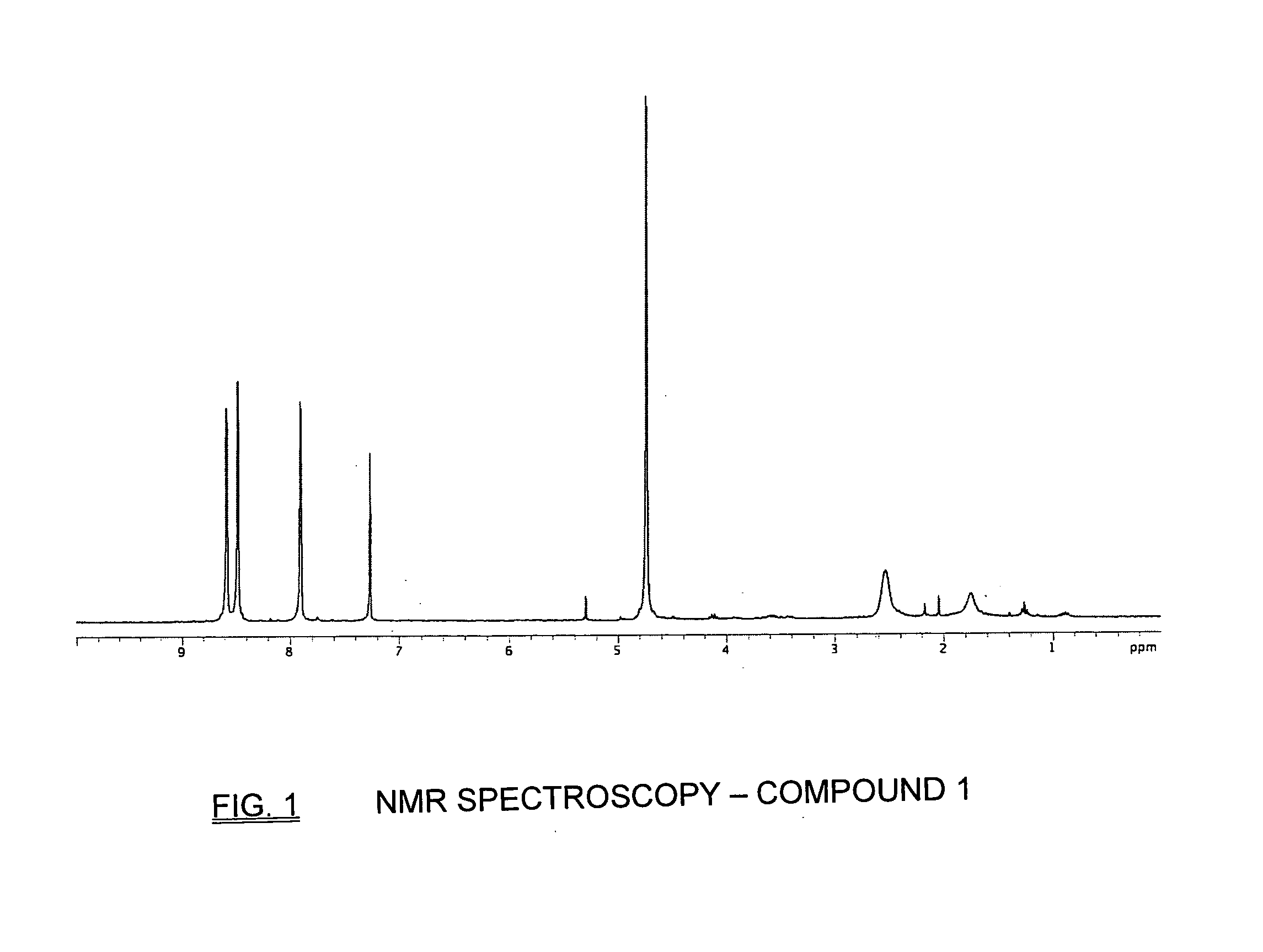
[0058]The components utilized in the synthesis of the cyclic siloxane are numbered as above. Methods of production for the components are described below. Each “compound” corresponds to the number in the above synthesis sequence.

[0059]Compound 1 was synthesized following the reported procedures as exemplified by the following references: Bachman, G. B.; Micucci, D. D. J. Am. Chem. Soc., 1948, 70, 2381-2384 and Zhang, N.; Tomizawa, M.; Casida, J. E. J. Med. Chem. 2002, 45, 2832-2840.
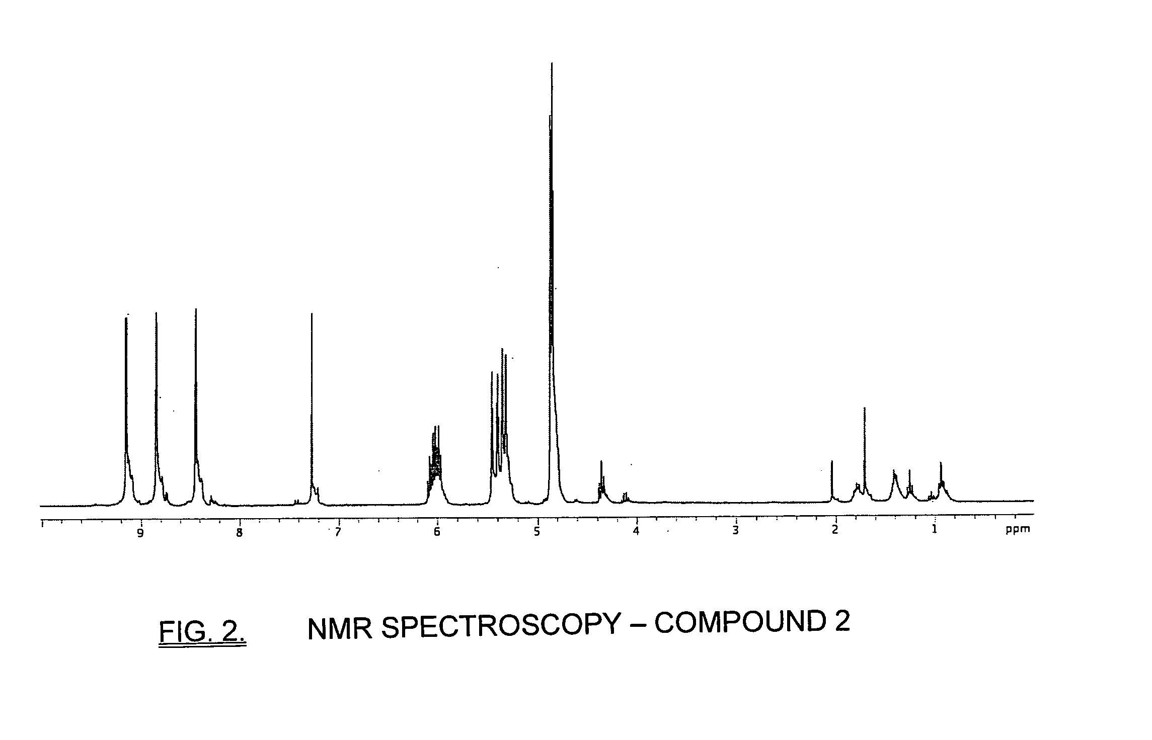
[0060]Compound 2

[0061]To a THF solution of NaH and compound 1 (1 g), a solution of allyl bromide in THF (10 ml) was added slowly. Then the mixture was heated to reflux for 20 hours. The reaction was quenched with 15 ml of water. The organic layer was separated, and the aqueous layer was extracted with THF (20 ml×2). The organic layer was combined and concentrated. Pure product was obtained as a colorless oil after column chromatography. (40% EA / Hexanes)
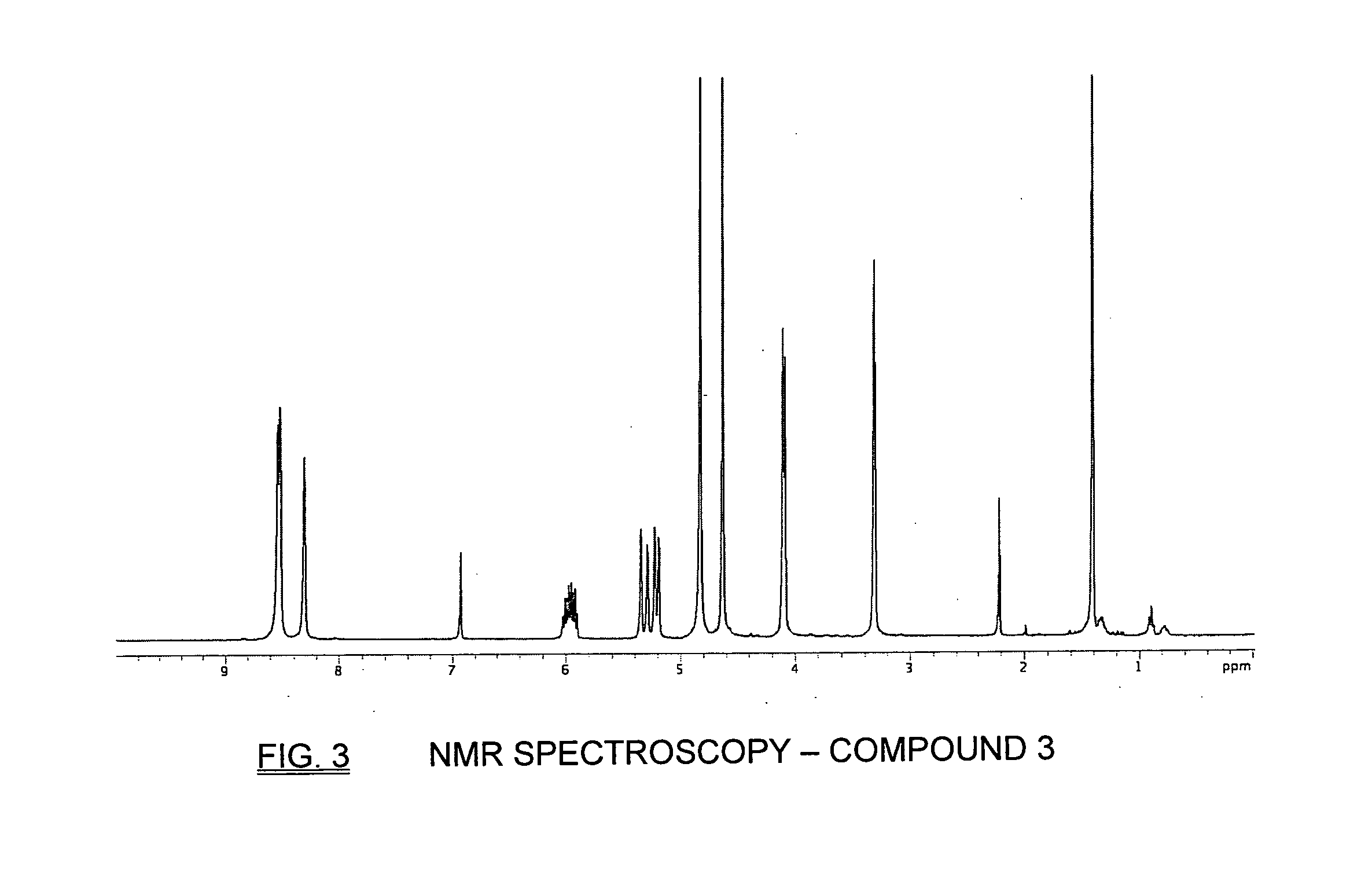
[0062]Compound 3

[0063]To a 500 m...


PUM


Abstract

A device and method for non-invasive real-time testing of blood sugar levels in a diabetic patient. Specifically, this invention is directed to an optical device comprising a contact lens having a glucose-sensing optical pattern imprinted, marked, coated or otherwise disposed on or incorporated within the contact lens. The indicator pattern is further comprised of a glucose-sensing coating containing a boronic acid derivative, which reacts in the presence of glucose to create a readable pattern, which can then be correlated to a pre-determined or pre-calibrated blood glucose level. A polarized light source is one method that may be used to read the indicator pattern. The invention is also directed to methods for quantifying blood glucose levels using the inventive optical device and manufacturing methods for disposing the glucose-sensing coating onto, or incorporating it into, the contact lens material.

Description

FIELD OF THE INVENTION[0001]This invention is directed to a device and method for non-invasive real-time testing of blood sugar levels in a diabetic patient. Specifically, this invention is directed to an optical device comprising a contact lens having a glucose-sensing optical pattern imprinted, marked, coated or otherwise disposed on or incorporated within the contact lens. The indicator pattern is further comprised of a glucose-sensing coating containing a boronic acid derivative, which reacts in the presence of glucose to create a readable pattern, which can then be correlated to a pre-determined or pre-calibrated blood glucose level. A polarized light source is one method that may be used to read the indicator pattern. The invention is also directed to methods for quantifying blood glucose levels using the inventive optical device and manufacturing methods for disposing the glucose-sensing coating onto, or incorporating it into, the contact lens material.BACKGROUND OF THE INVEN...

Claims


Application Information

Patent Timeline
Patent Type & Authority Applications(United States)
IPC IPC(8): A61K49/00
CPCA61B5/14532A61B5/14558B29D11/00125A61B5/6821G01N33/66G02C7/04B29D11/00317
Inventor HU, JUN JACK
Owner THE UNIVERSITY OF AKRON
Why Eureka
Try Eureka