Nanostructured composite reinforced material

a composite reinforced material and nanostructure technology, applied in the field of reinforced materials, can solve the problems of affecting the performance of nanotubes, so as to achieve significant performance enhancement, improve strength, and improve the effect of material properties

Active Publication Date: 2012-07-12
UT BATTELLE LLC +1
View PDF1 Cites 65 Cited by
  • Summary
  • Abstract
  • Description
  • Claims
  • Application Information

AI Technical Summary

Benefits of technology

[0014]The invention addresses the needs in the known art. What is provided is a family of materials wherein nanostructures and / or nanotubes are incorporated into a multi-component material arrangement, such as a metallic or ceramic alloy or composite / aggregate, producing a new super strong material or metallic / ceramic alloy. This new family of super strong materials provides significant performance enhancements due to superior material properties. Such superior properties include increased strengths up to and perhaps exceeding several thousand times normal, the upper bound of which has not yet been determined; improved elasticity, wear, electrical, corrosion, fatigue, and thermal characteristics; and improved strength-to-weight ratios. Such improved properties can revolutionize applications and provide materials for super strong structures such as: stronger steel beams for construction; power transmission cables that have high stiffness, high electrical conductance, and very low electrical loss; crash protection barriers; “light weight” materials for automotive and transportation components; and high performance coatings or surfaces.

Problems solved by technology

Whereas the two or more contributing materials in a composite material retain their own distinctive properties, the new composite material has properties which cannot be achieved by the individual components alone.
Dispersion strengthened composites have a fine distribution of particles embedded in the matrix and impede the mechanisms that allow a material to deform (including dislocation movement and slip).
The surface of a clean nanotube is “slippery”, that is, unlikely to provide an anchor for mechanical reinforcement or is unlikely to be wetted by the matrix material.

Method used


Image

  • Nanostructured composite reinforced material
  • Nanostructured composite reinforced material
  • Nanostructured composite reinforced material

Examples


Embodiment Construction

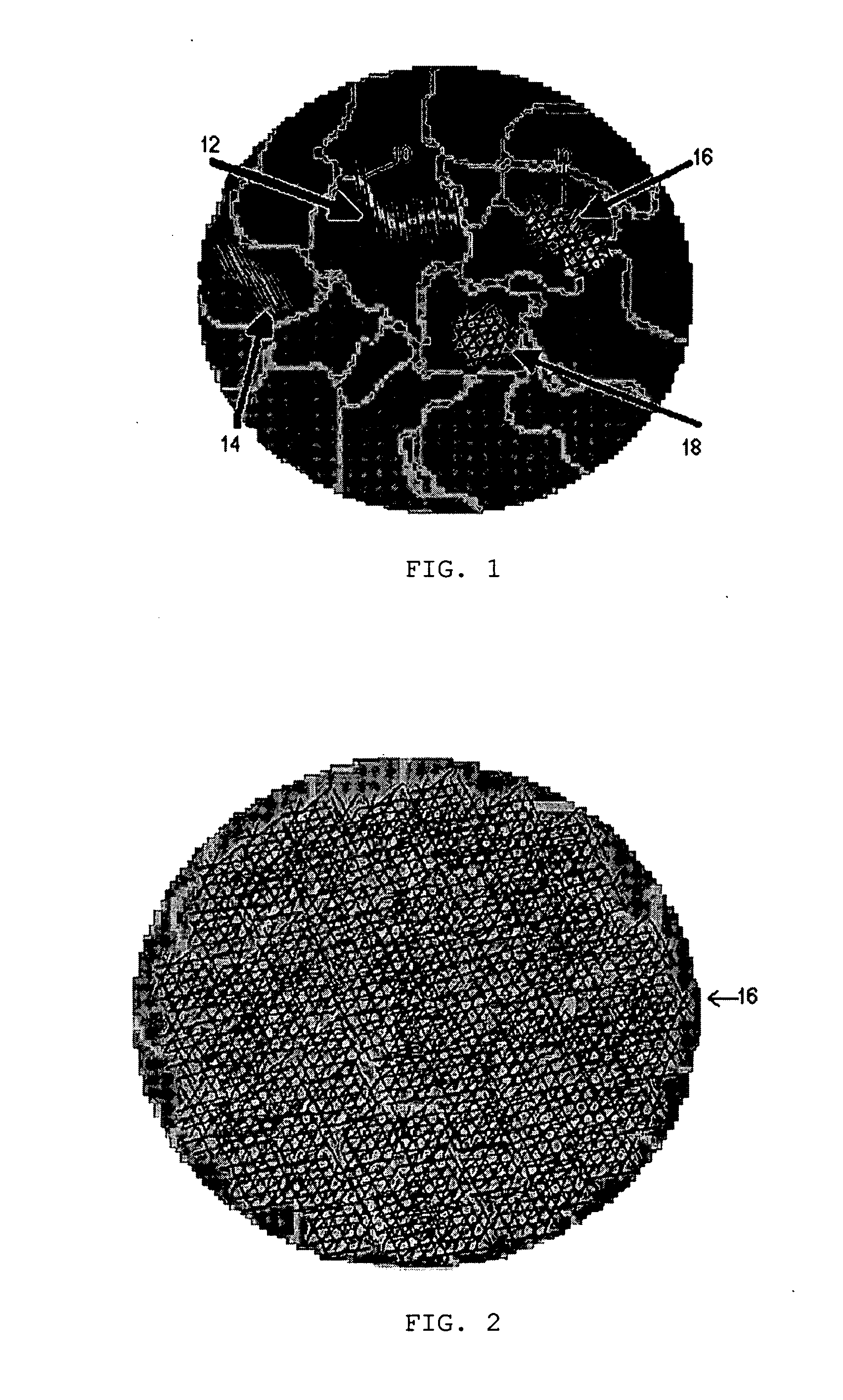
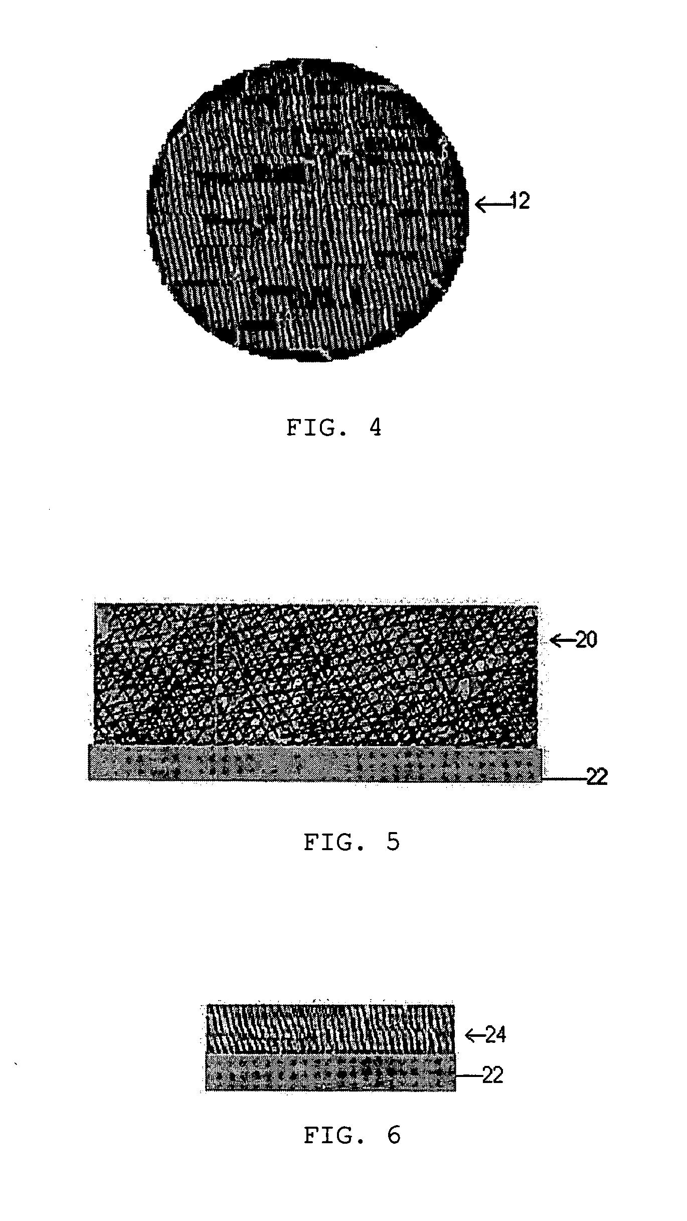
[0028]The invention is generally comprised of a material that has nanostructures and / or nanotubes incorporated into a multi-component material arrangement, such as a metallic or ceramic alloy or composite / aggregate.

[0029]The reinforced material may be manufactured as a component wherein the nanostructure or nanostructure reinforcement is incorporated into the bulk and / or matrix of the original material, or as a coating wherein the nanostructure or nanostructure reinforcement is incorporated into a coating or surface of the “normal” substrate material.

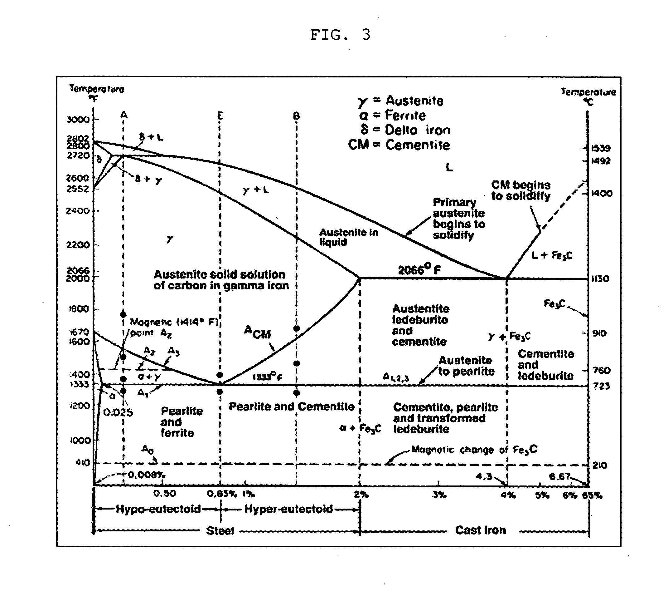
[0030]The metal alloys include, but are not limited to, iron-based materials, first-row metal alloys, second-row metal alloys, third-row metal alloys, and refractory metal alloys. The nanostructures and / or nanotubes include, but are not limited to, carbon, boron, and silicon-based materials. The nanostructures may be particles, nanotubes, single-walled nanotubes, multi-walled nanotubes, bundles of nanotubes, nanoropes, nanofibers, nanoh...


PUM

PropertyMeasurementUnit
length/diameteraaaaaaaaaa
diameteraaaaaaaaaa
aspect ratioaaaaaaaaaa

Abstract

A family of materials wherein nanostructures and / or nanotubes are incorporated into a multi-component material arrangement, such as a metallic or ceramic alloy or composite / aggregate, producing a new material or metallic / ceramic alloy. The new material has significantly increased strength, up to several thousands of times normal and perhaps substantially more, as well as significantly decreased weight. The new materials may be manufactured into a component where the nanostructure or nanostructure reinforcement is incorporated into the bulk and / or matrix material, or as a coating where the nanostructure or nanostructure reinforcement is incorporated into the coating or surface of a “normal” substrate material. The nanostructures are incorporated into the material structure either randomly or aligned, within grains, or along or across grain boundaries.

Description

BACKGROUND OF THE INVENTION[0001]1. Field of the Invention[0002]The invention is generally related to reinforced materials and more particularly to materials that are reinforced through the use of nanostructures to be super strong materials.[0003]2. General Background[0004]In the present state of the art, reinforced composites use particles or fibers which have micron-sized diameters. Fiberglass and carbon fiber composites are examples of fiber-reinforced composites. Typical fibers used in state-of-the-art composites have diameters greater than 0.0001-inches (2.54 microns) to 0.005-inches (30.4 microns), and length / diameter (L / D) ratios greater than 1 micron. Carbon fiber reinforcements are typically 5 to 8 microns diameter and grouped into tows or yarns of 2,000 to 12,000 fibers. The fiber modulus can range from 207 GPa to 960 GPa.[0005]A typical fiber-reinforced material combines the properties of the fiber material with those of the matrix material in which the fibers are embedde...

Claims


Application Information

Patent Timeline
Patent Type & Authority Applications(United States)
IPC IPC(8): B32B5/16B32B15/02C04B35/00B82Y30/00
CPCC22C47/08C22C49/08C22C47/14Y10T428/249921B22F7/04B22F2007/047C22C2026/002C22C26/00B22F7/08
Inventor SEALS, ROLAND D.RIPLEY, EDWARD B.LUDTKA, GERARD M.
Owner UT BATTELLE LLC
Why Eureka
Try Eureka