Nanofluidic cell

a technology of nanofluidic cells and nanotubes, applied in the field of nanofluidic cells, can solve the problems of reducing the fluid resistance of the cell, affecting the material stability of the cell, and limiting the length scale to 100 nm or less, so as to reduce the fluid resistance

Inactive Publication Date: 2012-07-19
INSIGHT NANOFLUIDICS
View PDF8 Cites 49 Cited by
  • Summary
  • Abstract
  • Description
  • Claims
  • Application Information

AI Technical Summary

Benefits of technology

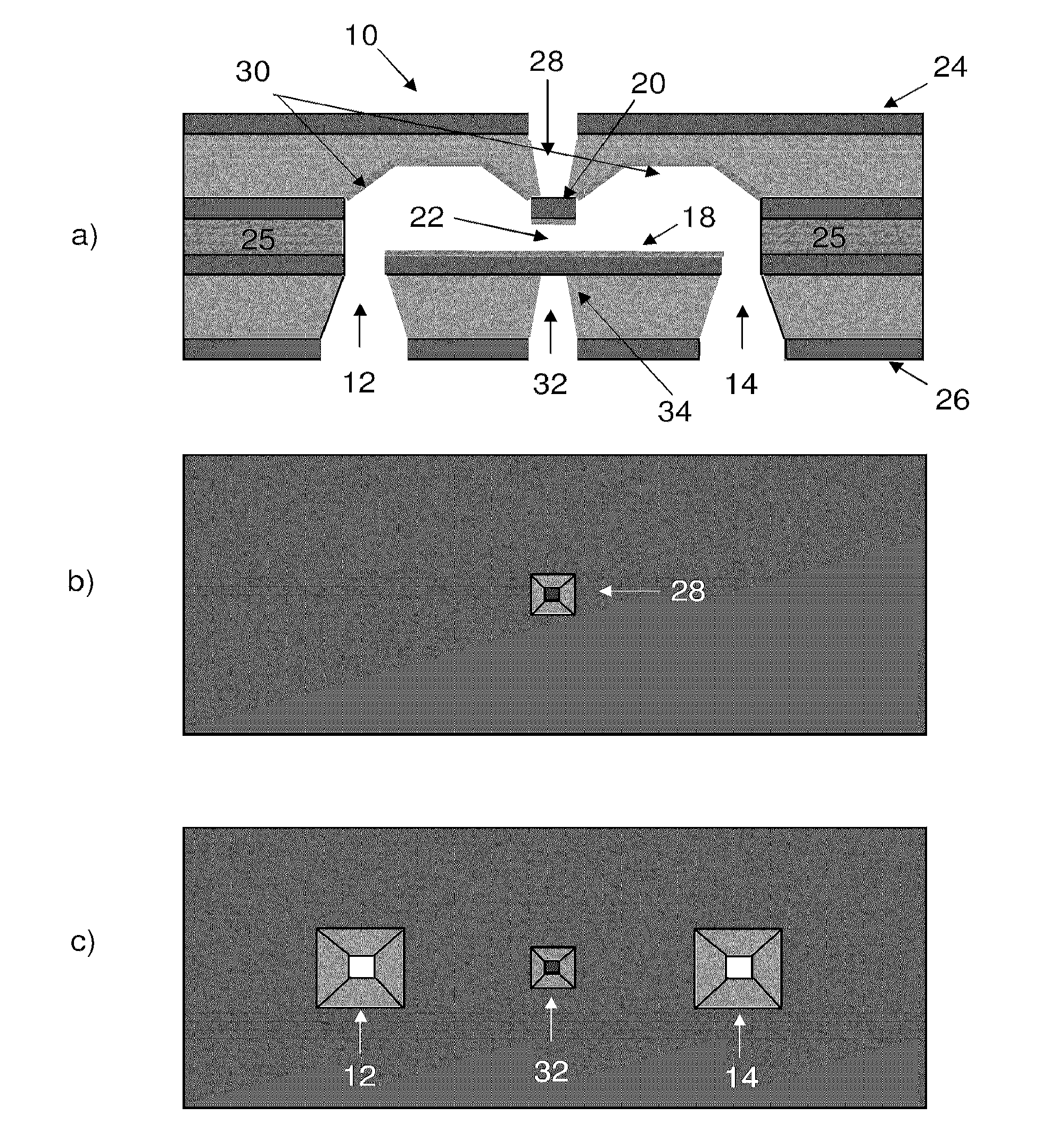
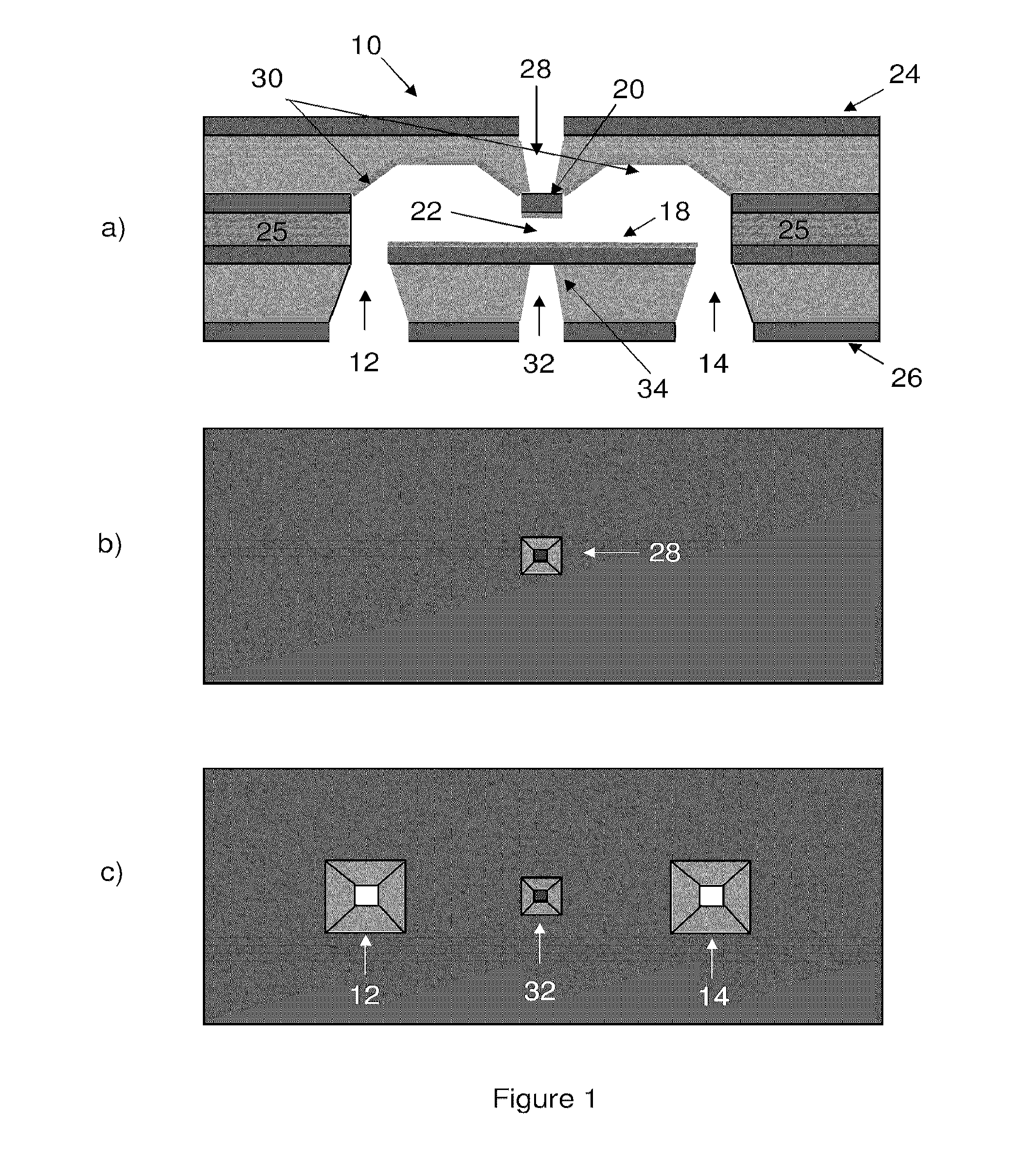
[0008]The present invention addresses this need by providing a flow cell that enables the probing of fluid samples. Furthermore, the flow cell is adapted for use with optical, x-ray, acoustic and electron analysis and/or microscopy by providing a device in which a membrane is included

Problems solved by technology

Unfortunately, the penetration depth of electrons, by virtue of their high scattering cross-section, is limited to 100 nm length scales or less.
This problem is particularly severe for electrons where one would like to image biological samples under aqueous condition

Method used


Image

  • Nanofluidic cell
  • Nanofluidic cell
  • Nanofluidic cell

Examples


Embodiment Construction

[0040]Generally speaking, the systems described herein are directed to a fluidic cell. As required, embodiments of the present invention are disclosed herein. However, the disclosed embodiments are merely exemplary, and it should be understood that the invention may be embodied in many various and alternative forms. The Figures are not to scale and some features may be exaggerated or minimized to show details of particular elements while related elements may have been eliminated to prevent obscuring novel aspects. Furthermore, various aspects of the invention may be further reduced in scale by using standard microfluidic concepts for flowing fluids involving micropumps and valves as a replacement of the macroscale syringe pumps shown in FIG. 6. Therefore, specific structural and functional details disclosed herein are not to be interpreted as limiting but merely as a basis for the claims and as a representative basis for teaching one skilled in the art to variously employ the presen...


PUM

PropertyMeasurementUnit
Areaaaaaaaaaaa
Thicknessaaaaaaaaaa
Pressureaaaaaaaaaa

Abstract

A flow cell is provided for the analysis and/or microscopy of liquid or gas samples on the nanometer to micron scale. The flow cell preferably includes a thin membrane that is transparent to electrons and/or photons, thereby enabling the penetration of electrons or photons into a liquid flowing through the cell. Trenches are provided on either side of the membrane, which advantageously minimize fluidic resistance outside of the window area of the cell and also enable a faster response time in response to changes in external fluidic pressure. This feature enables active feedback using pathlength sensitive probes to stabilize the fluid flow to thin streams from nanometer to micron scale thicknesses with nanometer precision.

Description

CROSS-REFERENCE TO RELATED APPLICATION[0001]This application claims priority to U.S. Provisional Application No. 61 / 227,893 titled “NANOFLUIDIC CELL” and filed on Jul. 23, 2009, the entire contents of which are incorporated herein by reference.FIELD OF THE INVENTION[0002]The present invention relates to devices and methods for the analysis of nanoliter or sub-nanoliter fluid volumes via analytical methods including electron, x-ray, and optical characterization.BACKGROUND OF THE INVENTION[0003]Microscopy and materials characterization methods typically employ light, electrons, acoustic waves and other forms of electromagnetic radiation to investigate optical, electronic and / or structural properties of a sample of interest.[0004]Electron microscopy is among the most powerful tools in resolving structure at the atomic level. Unlike its optical counterpart that is limited by the wavelength of visible light, electron microscopy utilizes electrons in the range of 10 keV to 1 MeV to probe ...

Claims


Application Information

Patent Timeline
IPC IPC(8): G01N1/10B32B37/14B32B37/02
CPCB82Y35/00G01N21/05G01N29/032G01N29/222G01N2223/637G01N2021/0346G01N2291/048H01J37/20H01J2237/2003H01J2237/2004G01N2291/02466
Inventor HARB, MAHERPAARMANN, ALEXDWYER, JASONMILLER, DWAYNE R. J.
Owner INSIGHT NANOFLUIDICS
Why Eureka
Try Eureka