
System for extraction and transport of light ashes by means of a steel belt conveyor

a belt conveyor and light ash technology, applied in transportation and packaging, combustion process, lighting and heating apparatus, etc., can solve the problems of minuscule droplets, fly ashes, extreme abrasives, etc., and achieve the effect of avoiding energy expenditure and system complexities associated with the use of known-art pneumatic transport systems

Inactive Publication Date: 2012-07-19
MAGALDI IND SRL
View PDF61 Cites 8 Cited by
  • Summary
  • Abstract
  • Description
  • Claims
  • Application Information

AI Technical Summary

Benefits of technology

[0013]First of all, the system drastically limits or eliminates relative motion between transported ashes and mechanical transport components, thereby reducing to a very significant extent or totally excluding all of the above-illustrated wear problems, associated both to known mechanical systems and to pneumatic ones.
[0014]Moreover, energy expenditures and system complexities associated to the use of known-art pneumatic transport systems are avoided.
[0017]In-boiler recycling of pulverized heavy ashes allows a remarkable reduction of the content of unburnt matters present therein. The reduction of unburnt matters in the heavy ashes thus treated, associated to grain size reduction and to the circumstance that, entrained by fumes, they are collected by the separation systems, allows—also due to the dilution effect operated to the other ash fraction—to lower the total percent of unburnt matters of light ashes and to make the latter suitable (according to the laws in force for their use) in the production of cement and concrete, avoiding drawing on the heritage of natural resources, above all limestone and pozzolana, obtained from dedicated quarries.
[0019]Hence, the above-mentioned configuration singles out an integrated system allowing transformation of all ashes produced inside the boiler into light (fly) ashes and subsequent mechanical transport into a unified transport and storage system, drastically reducing complexity and investment cost, and absorbed power value.

Problems solved by technology

Overall, such impurities form a fraction that melts in the combustion chamber, giving rise to minuscule droplets.
It should be noted that fly ashes have an average grain size ranging between 10 and 50 microns, low bulk density and low friction coefficient, and are extremely abrasive.
Owing to these features, they are extremely difficult to move downstream of the dedusting systems, both as hardly containable and owing to the high dustiness determined during said moving, especially at the hopper loading and unloading points.
Moreover, said ashes subject transport machine components to marked wear.
Chain conveyors—generally based on a system of vanes apt to push ash to a collection point and driven just by moving chains—entail the drawback of being subjected to wear consequent to relative motion of the highly abrasive material on the components of the conveyor itself, such as conveying chains, scrapers, casing bottom and walls.
The unforeseen failure of even a single element of a chain conveyor causes a sudden stop of the entire transport system, and therefore an interruption of the production of upstream and downstream systems for the time needed for maintenance or replacement of the damaged component.
Pneumatic moving systems are generally more reliable than the above chain systems, but consume far more power than the latter, having to move ashes, as well as transport air, and wear out more quickly in areas where ash grazes against transport pipes, valves and ejectors, due to the high rates required for pneumatic transport.
The effects of such wears are usually delayed by costly coatings of ceramic materials and with the use of basalt components located in the points of higher impact of the material along the transport duct, usually made of steel or special high-manganese cast irons.
Pneumatic systems entail remarkable energy consumption, due also to the power needed to grant the head useful for ash transport to the end storage silo or to other sites for subsequent ash treatment, and identify a complex system, also due to the presence of minor dedusting systems associated to the spent stream of transport air.

Method used


Image

  • System for extraction and transport of light ashes by means of a steel belt conveyor
  • System for extraction and transport of light ashes by means of a steel belt conveyor
  • System for extraction and transport of light ashes by means of a steel belt conveyor

Examples


Embodiment Construction

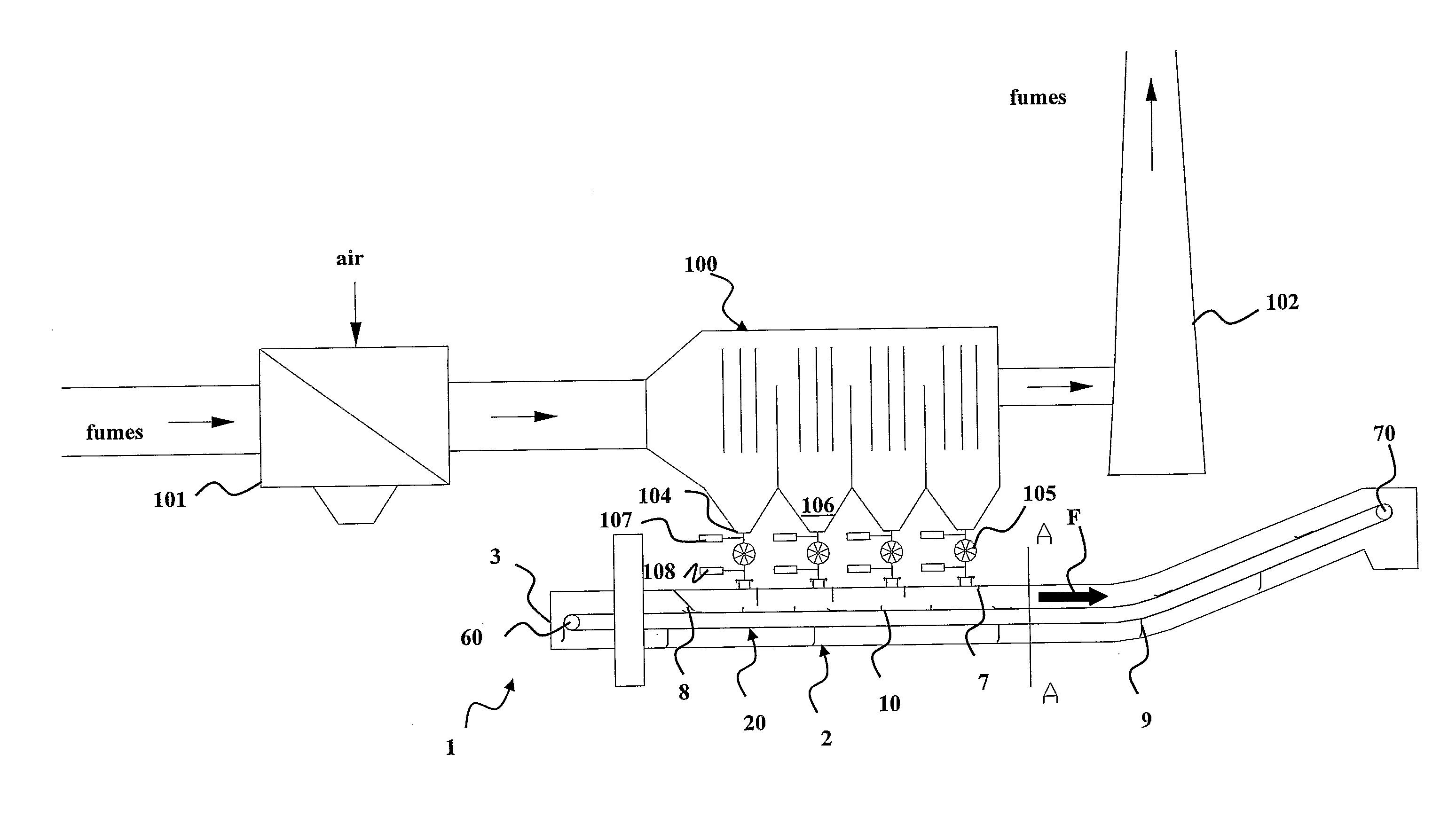
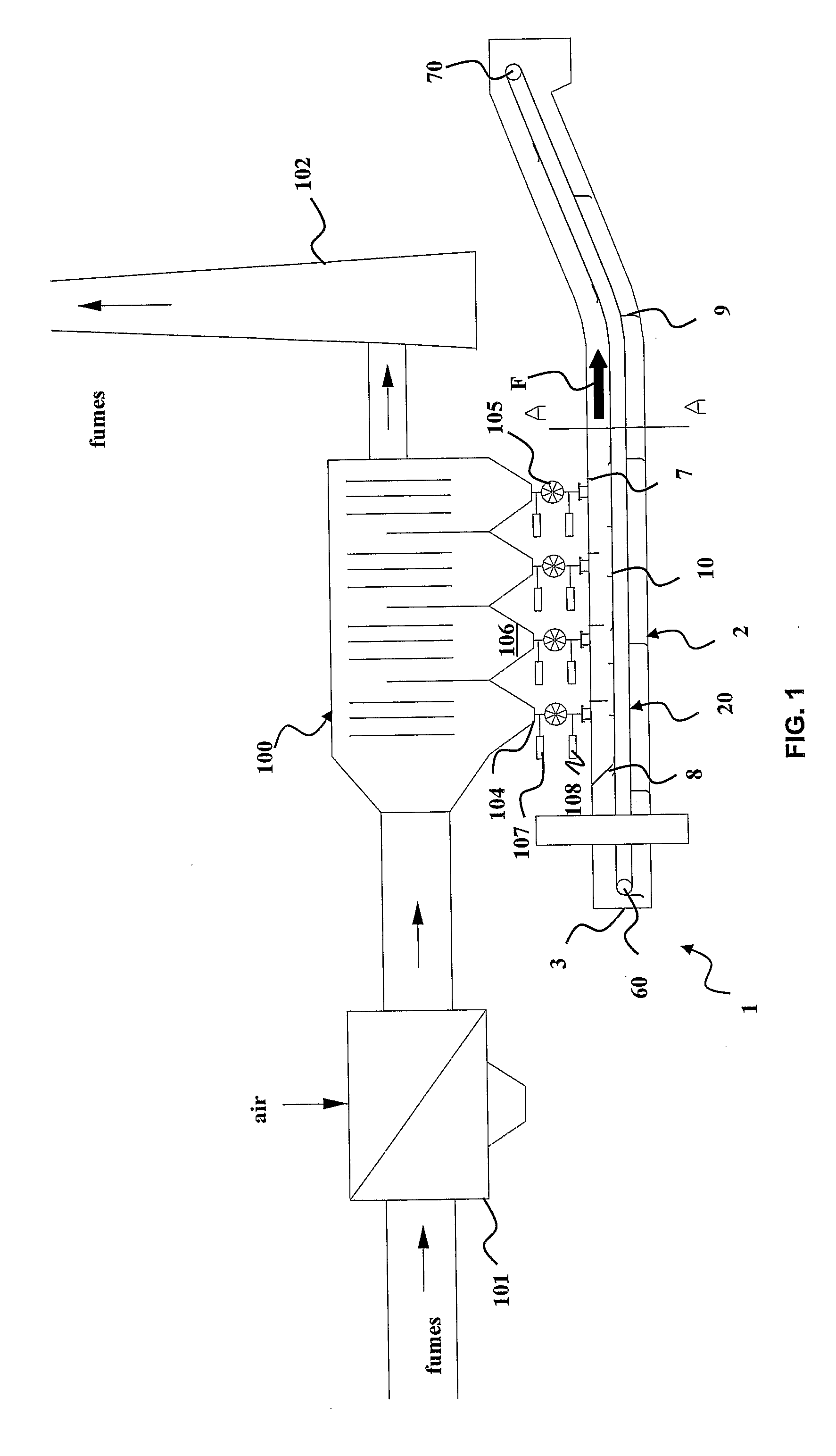
[0032]Referring initially to FIG. 1, an apparatus for dry transport of fly (light) ashes produced inside solid fuel boilers according to a preferred embodiment of the invention is generally denoted by 1.

[0033]The apparatus 1 is associated to a system for dedusting combustion fumes generated inside said boiler, generally denoted by 100, which in the present example is of the type employing an electrostatic principle for the separation of fly ashes from the fumes themselves.

[0034]In FIG. 1, apparatus 1 and system 100 are depicted as inserted in a typical context of an installation envisaging an air / fume exchanger 101 and a fumes exhaust stack 102, arranged respectively upstream and downstream of the fumes separation system 100.

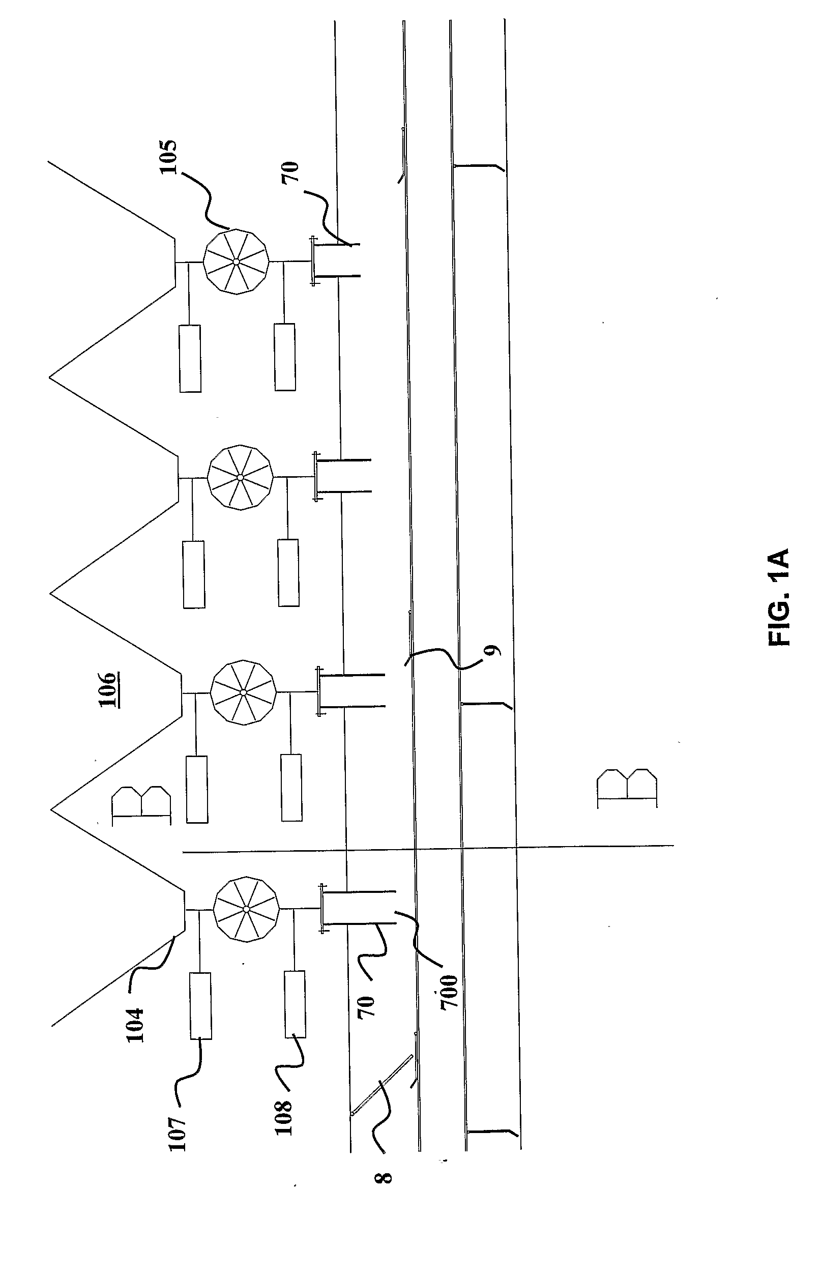
[0035]The apparatus 1 comprises first of all a metal belt 20 type conveyor 2, in particular made of steel. The belt 20 is apt to convey the fly ashes extracted from the fume dedusting system 100 to a storage, treatment and / or disposal site, and is enclosed in a ...


PUM


Abstract

A transport apparatus for dry extraction and transport of fly ashes produced inside solid fuel boilers, adapted to be associated with a fume dedusting system and including: a metal belt conveyor, having a plurality of slats partially overlapped, adapted to support a bed of fly ashes to transport the bed along a preset path, and a sealed metal casing inside which the slats move; and containment means for fly ashes, adapted to confine the ashes on the slats and along the transport path so as to limit relative motion between ashes and conveyor, which means comprises transverse boards, leveling members, side boards and a movable rear baffle.

Description

FIELD OF THE INVENTION[0001]The present invention refers to a system for dry extraction and transport of light ashes produced inside solid fuel boilers, where the transport system is based on a belt conveyor, preferably made of steel.BACKGROUND OF THE INVENTION[0002]Coal ashes are the product of a transformation undergone by mineral impurities, above all silica, present in fossil fuel following its combustion in thermoelectric plants. Overall, such impurities form a fraction that melts in the combustion chamber, giving rise to minuscule droplets. The latter, entrained by fumes, at the boiler outlet undergo a sudden cooling and solidify in the form of vitreous particles of spheroid shape. Dust abatement systems then purify the fumes, separating therefrom these ashes that are defined “light” or “fly” ashes, to tell them apart from that minor fraction of impurities that, by agglomerating, falls directly on the boiler bottom (“heavy” ashes)[0003]Known systems for dedusting combustion fu...

Claims


Application Information

Patent Timeline
IPC IPC(8): F23J3/00B65G17/06
CPCB65G17/067F23J3/06B65G47/19B65G17/46B65G17/06
Inventor MAGALDI, MARIO
Owner MAGALDI IND SRL
Learn More