Field Device for Process Instrumentation

a field device and process instrument technology, applied in the field of process instruments, can solve the problems of reducing the power available for supplying electronics by a further 3%, unable to produce drive current, and amplifiers with a comparatively high power consumption, so as to reduce the current drawn by the output stage, reduce disturbances, and reduce the effect of curren

Active Publication Date: 2012-07-26
SIEMENS AG
View PDF2 Cites 5 Cited by
  • Summary
  • Abstract
  • Description
  • Claims
  • Application Information

AI Technical Summary

Benefits of technology

[0015]It is therefore an object of the invention to provide a field device for process instrumentation, whose output stage has a comparatively low power consumption, and which nevertheless is relatively insensitive to electromagnetic disturbances.
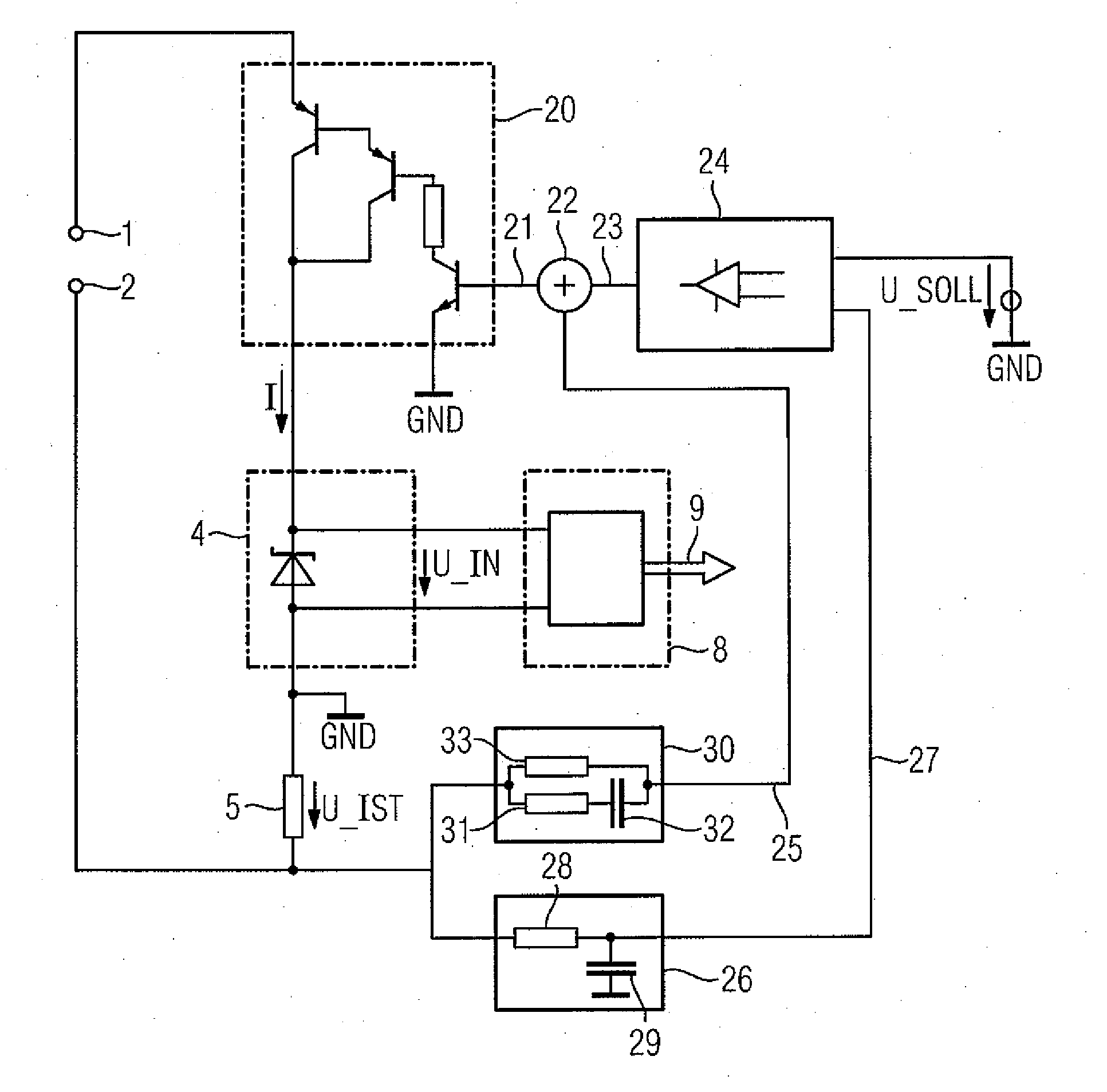
[0016]This and other objects and advantages are achieved in accordance with the invention by providing a field device in which injected disturbances can be advantageously compensated for via the two-wire line without having to place any particular requirements on the speed of the regulator, which is used to drive the transistor circuit. Effectively, a subordinate, second control loop is formed to suppress disturbances injected via the two-wire line, by passing a second feedback path with a compensation signal directly, and not via the regulator with an integrating behavior, to a transistor circuit for adjusting the loop current. EMC disturbances are therefore filtered by an internal, rapid control loop, and the operational amplifier used in the regulator can be designed to be considerably slower. It is therefore possible to use an operational amplifier which draws considerably less current. The current drawn by the output stage can furthermore be reduced further by the introduction of a second feedback path for suppression of injected disturbances, by using a transistor circuit with a considerably higher gain. The gain factor may, for example, now be 50,000, as a result of which no further appreciable power loss as a result of the drive current for the transistor circuit occurs.
[0018]In one particularly advantageous embodiment, a proportional element for superimposition of a component that is proportional to the loop current is connected in parallel with the high-pass filter in the second feedback path. This feedback path, which can also be referred to as DC feedback, reduces the gain of the transistor circuit. This reduction in the gain advantageously amplifies the output noise from the regulator to a lesser extent. The requirements for the noise behavior of the regulator are therefore less critical than if the parallel-connected proportional element were to be dispensed with, without the gain of the transistor circuit still needing to be high, without any change. On the other hand, the parallel-connected proportional element makes it possible to use an operational amplifier in the electronic circuit of the regulator, which has higher self-noise and is therefore commercially available more cheaply.
[0019]Disturbances injected via the two-wire line are advantageously suppressed by the rapid, subordinate control loop. As a result, this is no longer the task of the regulator in the outer control loop. As already mentioned above, this has the advantage that the rapidity of the regulator is no longer subject to stringent requirements. However, if a regulator with a medium bandwidth is used, it may be worthwhile to use a low-pass filter in the first feedback path to keep EMC disturbances in the medium frequency range, for example, in a range from 10 kHz to 1 MHz, away from the regulator input. This results in complete functional isolation, specifically in that the rapid, subordinate control loop is used to suppress the EMC disturbances, and in that the regulator in the outer control loop is exclusively responsible for the accuracy of the measured-value output with an analogue current signal. An ultra-low-power operational amplifier with high accuracy can be used, such as the LMP2231 Type from National Semiconductor, or the AD8603 Type from Analog Devices. The two control loops can be optimally matched to their respective function.
[0020]The use of a transistor circuit with a Darlington stage has the advantage that the transistor circuit has a considerably higher gain, which is in the order of magnitude of 50 000, and that, in consequence, only a very low signal power level is required to operate the transistor circuit. The sensitivity of a transistor circuit having a high gain such as this to injected EMC disturbances is not critical because of the rapid, subordinate control loop that is used to suppress disturbances injected via the two-wire line. The regulator in the outer control loop need no longer react to the EMC disturbances. Despite the high gain of the transistor circuit, it is possible to use a regulator with a low bandwidth, which is distinguished by drawing a relatively low current.

Problems solved by technology

The drive current is therefore no longer available for producing the power required for operating the measurement transducer.
This can be achieved only by an operational amplifier that has a comparatively high power consumption.
In comparison to the use of an ultra-low-power version, this results in a reduction in the power available for supplying the electronics by a further 3%.

Method used


Image

  • Field Device for Process Instrumentation
  • Field Device for Process Instrumentation
  • Field Device for Process Instrumentation

Examples


Embodiment Construction

[0025]As already explained in more detail above, FIG. 1 shows an outline circuit of an output stage of a 4-20 mA interface as is used in a conventional SITRAS P pressure measurement transducer.

[0026]Many parts of the known output stage shown in FIG. 1 are shown again in the exemplary embodiment of an output stage in FIG. 2. These are provided with the same reference symbols in both figures.

[0027]A transistor circuit 20 that contains a Darlington stage is now used in the output stage shown in FIG. 2. This Darlington circuit is distinguished by a considerably higher gain, thus allowing a signal 21 with relatively low signal power to be used to operate it. In the illustrated exemplary embodiment, the signal 21 is produced by a summation point 22 to which a control signal 23, which is output from a regulator 24, and a compensation signal 25 are passed. The measurement resistor 5 is used in the known manner as a way to detect the loop current I as an actual value U_ACT. This actual value...


PUM


Abstract

A field device for process instrumentation having an interface for connecting a two-wire cable and for outputting measurement values, wherein the interface comprises a series circuit having a transistor circuit by which the loop current is adjustable as a function of a control signal, a power supply, and a device by which the loop current can be captured as an actual value that is fed by a first feedback coupling to a regulator having integrated behavior. The regulator compares the actual value to a target value, and generates a control signal for the transistor circuit. The actual value is fed by a second feedback coupling to a summation point as a compensation signal for generating an input signal for the transistor circuit as a function of the control signal and the compensation signal to suppress interference coupled into the two-conductor line.

Description

CROSS-REFERENCE TO RELATED APPLICATIONS[0001]This is a U.S. national stage of application No. PCT / EP2010 / 059534 filed 5 Jul. 2010. Priority is claimed on German Application No. 10 2009 034 419.5 filed 23 Jul. 2009, the content of which is incorporated herein by reference in its entirety.BACKGROUND OF THE INVENTION[0002]1. Field of the Invention[0003]The invention relates to process instrumentation and, more particularly, to a field device for process instrumentation, which has a standardized 4-20 mA interface for outputting measured values.[0004]2. Description of the Related Art[0005]Versatile field devices are used for process instrumentation for controlling processes in process installations. Measurement transducers are used to detect process variables, such as temperature, pressure, flow rate, filling level, density or gas concentration of a medium. The process sequence can be influenced by actuating elements, as a function of detected process variables, corresponding to a strate...

Claims


Application Information

Patent Timeline
Patent Type & Authority Applications(United States)
IPC IPC(8): G05F1/10
CPCG05B2219/25428G01D3/02
Inventor BACHMANN, REINHARDCHEMISKY, ERICGEPPERT, MICHAELROHRBACH, SIMONWALTER, RALF
Owner SIEMENS AG
Why Eureka
Try Eureka