Transparent substrate

a transparent substrate and substrate technology, applied in the field of transparent substrates, can solve the problems of increasing resistance value or disconnection, unable to obtain display devices with sufficient display performance, and unable to handle glass substrates, etc., to prevent the progress of cracks and excellent bending properties and flexibility.

Active Publication Date: 2012-08-02
NITTO DENKO CORP
View PDF8 Cites 46 Cited by
  • Summary
  • Abstract
  • Description
  • Claims
  • Application Information

AI Technical Summary

Benefits of technology

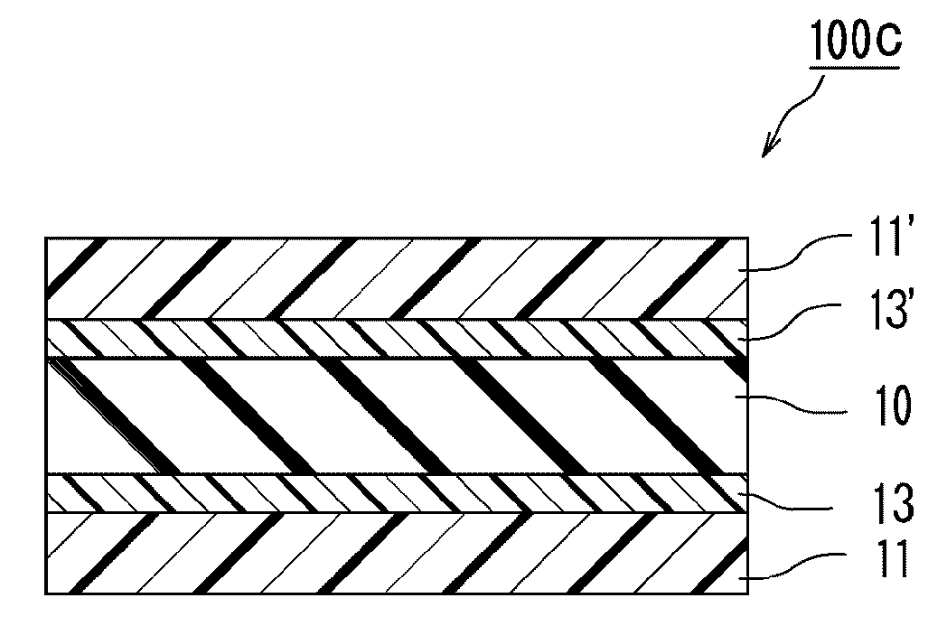
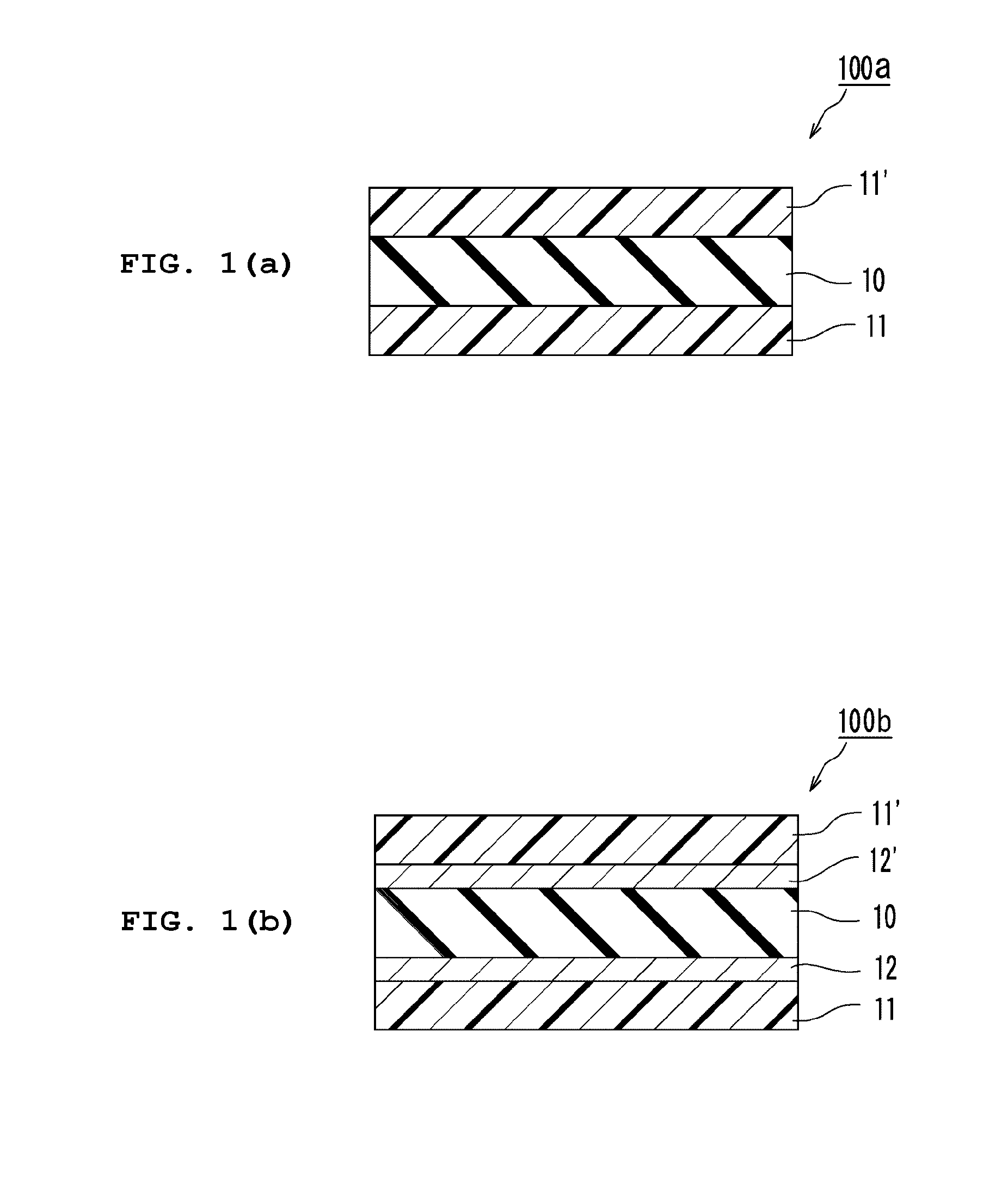
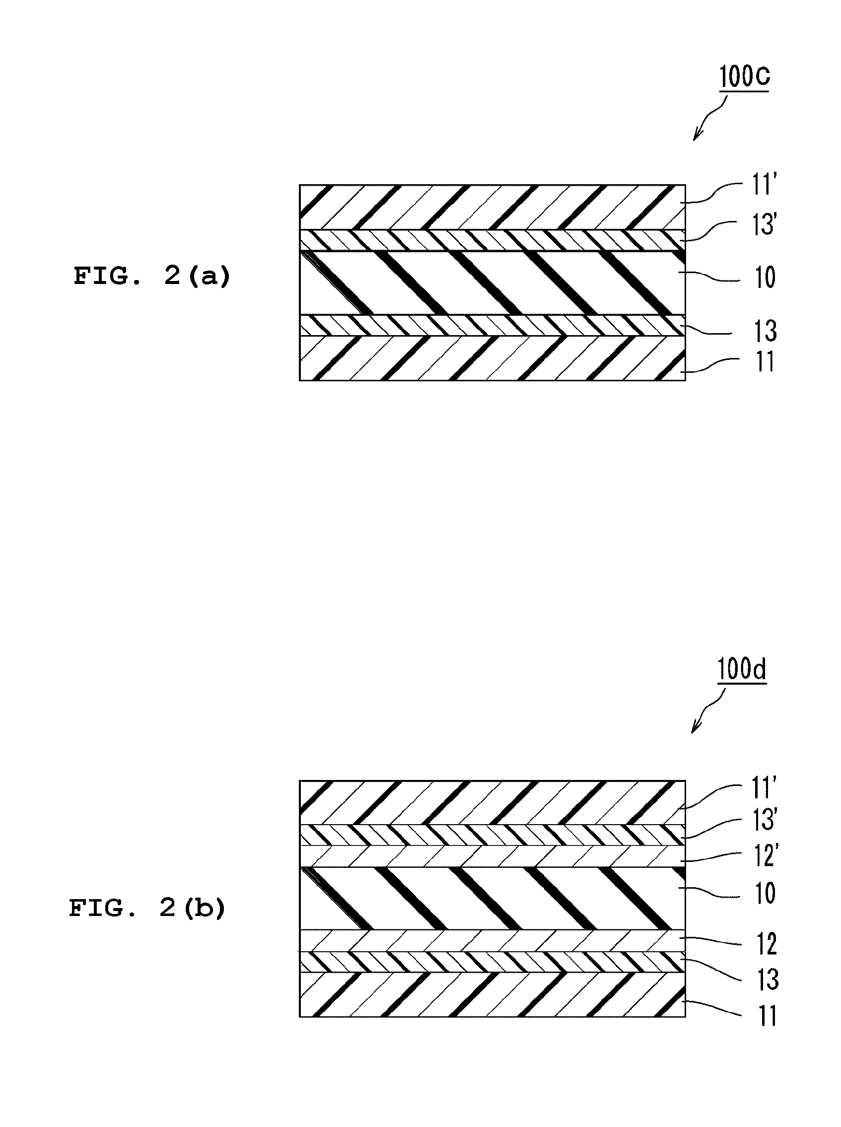
[0023]According to the present invention, there can be provided the following transparent substrate. The transparent substrate includes a resin layer having a specific shrinkage stress on at least one side of a thin-plate glass to reinforce the thin-plate glass, thereby significantly preventing the progress of a crack in the thin-plate glass and the rupture of the glass. In addition, the transparent substrate is excellent in bending property and flexibility.

Problems solved by technology

However, when one attempts to achieve the weight reduction and thinning of a glass material, which forms such glass substrate, the following problem arises.
That is, though the glass substrate shows some degree of bending property, the brittleness of glass against a crack or the like is conspicuously exhibited, and hence the glass substrate becomes difficult to handle.
However, a resin for constructing the resin film has a higher coefficient of thermal expansion than that of an inorganic material such as the glass, and hence the substrate for a display device obtained by using the resin film involves the following problems.
The distortion of the substrate occurs, or a crack occurs in an electrode at the time of the formation of a circuit to cause an increase in resistance value or disconnection.
In addition, when a resin having an aromatic ring and / or a heterocycle introduced into its main chain for improving its heat resistance is used, the resin film undergoes coloring and hence a display device having sufficient display performance cannot be obtained.
However, such resin cannot provide a substrate for a display device having sufficient dimensional stability because its coefficient of linear expansion is about ten times as high as that of the glass.
Further, the resin film does not have sufficient gas barrier property.
As a result, a problem such as an increase in the number of production steps, a reduction in yield, or an increase in cost arises.
However, it has still been unable to obtain a transparent substrate showing sufficient bending property even with such technology because the technology is insufficient in terms of the optimization of a resin material for reinforcing the glass.

Method used


Image

  • Transparent substrate
  • Transparent substrate
  • Transparent substrate

Examples


example 1

[0118]A polyether sulfone (Sumika Excel 5003P manufactured by Sumitomo Chemical Company, Limited), cyclopentanone, dimethyl sulfoxide, and a leveling agent (BYK-307 manufactured by BYK-Chemie) were mixing at a weight ratio (polyether sulfone:cyclopentanone:dimethyl sulfoxide:leveling agent) of 140:658:42:0.105. Thus, a casting solution (A) was obtained.

[0119]Separately, one surface of a thin-plate glass measuring 50 μm thick by 30 mm wide by 100 mm long was washed with methyl ethyl ketone, and was then subjected to a corona treatment. Subsequently, an epoxy group-terminated coupling agent (KBM-403 manufactured by Shin-Etsu Chemical Co., Ltd.) was applied to the surface, and was then subjected to a heat treatment at 110° C. for 5 minutes. The casting solution (A) was applied to the surface of the thin-plate glass subjected to the coupling treatment as described above, and was then dried at 70° C. for 4 minutes, at 150° C. for 4 minutes, and at 200° C. for 10 minutes. Thus, a resin la...

example 2

[0121]A polyarylate (U-100 manufactured by Unitika Limited), trichloroethane, and a leveling agent (BYK-302 manufactured by BYK-Chemie) were mixed at a weight ratio (polyarylate:trichloroethane:leveling agent) of 15:85:0.1. Thus, a casting solution (B) was obtained.

[0122]The casting solution (B) was applied to the surface of a polyethylene terephthalate film, and was then dried at 110° C. for 12 minutes. After that, the polyethylene terephthalate film was released. Thus, a resin film having a thickness of 35 μm was obtained.

[0123]A mixed solution obtained by mixing an epoxy-based resin (CELLOXIDE 2021P manufactured by Daicel Chemical Industries, Ltd.), an oxetane-based resin (OXT-221 manufactured by Toagosei Company, Limited), and a polymerization initiator (ADEKA OPTOMER SP-170 manufactured by ADEKA CORPORATION) at a weight ratio (epoxy-based resin:oxetane-based resin:polymerization initiator) of 90:10:3 was applied to the resin film. After that, the solution was dried at 40° C. fo...

example 3

[0126]A transparent substrate was obtained by placing a hard coat layer having a thickness of 3 μm on the side of the resin layer of the transparent substrate obtained in Example 1 opposite to the thin-plate glass. The hard coat layer was formed by: applying, to the surface of the resin layer, a mixed liquid of 75 parts of an epoxy-based resin (CELLOXIDE 2021P manufactured by Daicel Chemical Industries, Ltd.), 25 parts of an epoxy-based resin (EHPE 3150 manufactured by Daicel Chemical Industries, Ltd.), and 3 parts of a polymerization initiator (ADEKA OPTOMER SP-170 manufactured by ADEKA CORPORATION); and irradiating the applied liquid with UV light from a high-pressure mercury lamp (intensity: 400 mJ / cm2 or more) to cure the applied liquid.


PUM

PropertyMeasurementUnit
thicknessaaaaaaaaaa
shrinkage stressaaaaaaaaaa
glass transition temperatureaaaaaaaaaa

Abstract

The present invention provides a transparent substrate that significantly prevents the progress of a crack in a thin-plate glass and the rupture of the glass, and is excellent in bending property and flexibility. A transparent substrate according to an embodiment of the present invention includes: a thin-plate glass having a thickness of 10 μm to 100 μm; and a resin layer on at least one side of the thin-plate glass, wherein a shrinkage stress of the resin layer on the thin-plate glass is 5 MPa or more.

Description

TECHNICAL FIELD[0001]The present invention relates to a transparent substrate. More specifically, the present invention relates to a transparent substrate that significantly prevents the progress of a crack in a thin-plate glass and the rupture of the glass, and is excellent in bending property and flexibility.BACKGROUND ART[0002]In recent years, display apparatus such as flat panel displays (FPDs: liquid crystal display apparatus, organic EL display apparatus, and the like) and a solar cell have been made more and more flexible from the viewpoints of, for example, easy conveyance, storing easiness, and design property, and the weight reduction and thinning of the transparent substrate to be used in the display apparatus and the solar cell, and in addition, an improvement in bending property thereof have been requested. Glass substrates have been conventionally used in many cases as transparent substrates for use in the display apparatus and the solar cells. The glass substrate is e...

Claims


Application Information

Patent Timeline
Patent Type & Authority Applications(United States)
IPC IPC(8): B32B17/10B05D3/10B31B1/62B32B7/02B31B50/62
CPCC03C17/32C03C17/3405C03C2218/365G02F2001/133302B32B17/064B32B2307/412Y10T428/266B32B2307/542B32B2307/544B32B2307/546Y10T428/2495Y10T156/10B32B2307/536B32B17/10G02F1/133302B32B17/04G02F1/1333G09F9/30
Inventor MURASHIGE, TAKESHIHATTORI, DAISUKESAKATA, YOSHIMASAYAMAOKA, TAKASHINAGATSUKA, TATSUKI
Owner NITTO DENKO CORP
Why Eureka
Try Eureka