Acoustic sensor and microphone

a technology of acoustic sensor and microphone, which is applied in the direction of diaphragm construction, semiconductor electrostatic transducer, microphone structural association, etc., can solve the problems of thermal noise generated in the air gap formed between the diaphragm (movable electrode plate) and the back plate (fixed electrode plate) of the diaphragm, and achieve the effect of improving the s/n ratio of the sensor and preventing the reduction in the size of the sensor

Active Publication Date: 2012-08-23
MMI SEMICON CO LTD
View PDF3 Cites 41 Cited by
  • Summary
  • Abstract
  • Description
  • Claims
  • Application Information

AI Technical Summary

Benefits of technology

[0021]The present invention was made in view of the technical problems as described above, and has an object to provide an acoustic sensor capable of improving an S / N ratio of a sensor without preventing reduction in size of the sensor, and a microphone using the acoustic sensor.

Problems solved by technology

However, in the former method of widening the area of the diaphragm, reduction in size of the acoustic sensor is hindered.
Further, in such a method of decreasing the spring properties of the diaphragm as the latter method, since the displacement amount of the diaphragm increases, durability of the acoustic sensor decreases.
As the noise of the acoustic sensor of the capacitance type, thermal noise generated in an air gap formed between the diaphragm (movable electrode plate) and a back plate (fixed electrode plate) are problematical.
Especially in a highly sensitive acoustic sensor or microphone, noise attributed to such thermal noise is large, and the S / N ratio thus deteriorates.
For this reason, with the method of simply reducing noise, the sensitivity of the acoustic sensor decreases simultaneously with reduction in noise, and hence it has not been possible to improve the S / N ratio of the acoustic sensor.
However, making characteristics of the acoustic sensors, separately formed on the same substrate, identical is difficult.
It has thus been difficult in practice to improve the S / N ratio in such a microphone as in Patent Document 2.
Further, in such a microphone, noise derived from mismatching tends to be generated, and hence there are limitations on improvement in S / N ratio.
Moreover, an extra computing function needs to be added to the signal processing circuit, which results in high cost of the signal processing circuit.
There has also been a problem in that reduction in size of the microphone is difficult because of the need to provide a plurality of acoustic sensors on the substrate.
However, even the microphone described in Patent Document 2 has a problem as follows.
Since warpage that occurs in the diaphragm in the microphone producing process varies, variations in sensitivity among each acoustic sensor tend to be large.
On the other hand, when the variations are intended to be made smaller, the productivity of the microphone decreases.
Further, there has been a problem in that, when the electrode leader connecting each of the acoustic sensors and the signal processing circuit on the substrate becomes longer, a parasitic capacitance and parasitic resistance of the microphone become larger, to cause deterioration in characteristics such as the sensitivity.
Moreover, since the plurality of independent acoustic sensors are provided, disagreement of the acoustic characteristics other than the sensitivity tend to occur among each sensor.
In the microphone of Patent Document 2, variations in sensitivity and other acoustic characteristics in each acoustic sensor tend to occur as thus described, and it has thus been difficult in practice to obtain the effect of improvement in S / N ratio.
Further, since the plurality of independent acoustic sensors need to be arranged in array on the substrate, there has been a problem of the microphone being not reducible in size.

Method used


Image

  • Acoustic sensor and microphone
  • Acoustic sensor and microphone
  • Acoustic sensor and microphone

Examples


first embodiment

[0063]A structure of an acoustic sensor according to Embodiment 1 of the present invention will be described with reference to FIGS. 4 to 6. FIG. 4 is a sectional view showing an acoustic sensor 41 of Embodiment 1. FIG. 5 is a plan view of the acoustic sensor 41. Further, FIG. 6 is a plan view showing a state where a canopy section 44 has been removed from the acoustic sensor 41.

[0064]This acoustic sensor 41 is a capacitance type element produced through use of the MEMS technique. As shown in FIG. 4, in the acoustic sensor 41, a diaphragm 43 (vibration electrode plate) is provided on the top surface of a silicon substrate 42 (semiconductor substrate) via an anchor 46, and to the top thereof, the canopy section 44 is fixed via a minute air gap 50 (void).

[0065]In the silicon substrate 42 made up of single-crystal silicon, a back chamber 45 (hollow section) penetrating from the front surface to the back surface is opened. The inner peripheral surface of the back chamber 45 may be a ver...

second embodiment

[0110]FIG. 12 is a plan view of an acoustic sensor 61 according to Embodiment 2 of the present invention. FIG. 13 is a plan view of the acoustic sensor 61 in a state where the canopy section 44 has been removed.

[0111]In the acoustic sensor 61 of Embodiment 2, a plurality of (three in the illustrative example) slits 47 are provided in the diaphragm 43, to divide the diaphragm 43 into not less than three areas (four areas in the illustrative example) so as to provide a plurality of substantially independent diaphragms 43a, 43b, . . . . Then, each of the diaphragms 43a, 43b, . . . and the common fixed electrode plate 49 constitute a plurality of acoustic sensing sections 60a, 60b, . . . (capacitors).

[0112]The acoustic sensor 61 of Embodiment 2 is one where the number of division of the diaphragm 43 is larger than that in the acoustic sensor 41 of Embodiment 1. Even when the number of slits 47 increases to increase the number of division of diaphragm 43 in such a manner (the shape and a...

third embodiment

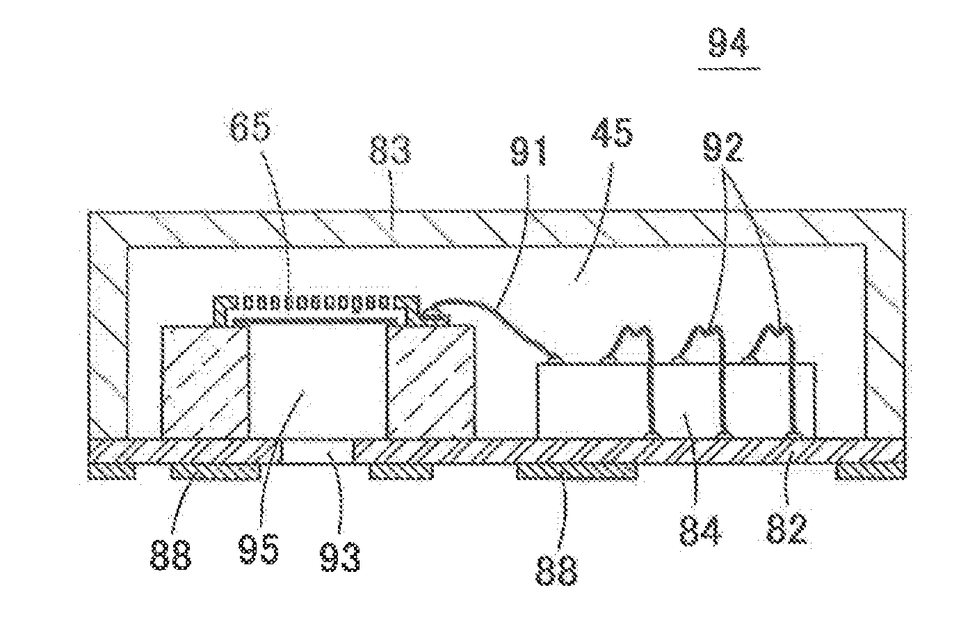
[0113]FIG. 14 is a sectional view of an acoustic sensor 62 according to Embodiment 3 of the present invention. FIG. 15 is a plan view of the acoustic sensor 62 of Embodiment 3.

[0114]In the acoustic sensor 62 of Embodiment 3, the diaphragm 43 is not supported by the anchors 46 as in Embodiment 1, but is simply placed on the top surface of the silicon substrate 42. On the other hand, from a position opposed to the outer periphery of the diaphragm 43 out of the under surface of the back plate 48, a protrusion 71 to be brought into contact with the top surface of the diaphragm 43 is protruded downward. Therefore, when a voltage is applied between the diaphragm 43 and the fixed electrode plate 49, the diaphragm 43 is pulled up by electrostatic attractive force toward the fixed electrode plate 49. The diaphragm 43 pulled up upward comes into contact with the lower end surface of the protrusion 71 and is fixed thereto, and the fixed air gap 50 is formed between the diaphragm 43 and the fix...


PUM


Abstract

Provided is an acoustic sensor capable of improving an S/N ratio of a sensor without preventing reduction in size of the sensor. A back chamber 45 is vertically opened in a silicon substrate 42. A thin film-like diaphragm 43 to serve as a movable electrode plate is formed on the top surface of the substrate 42 so as to cover the back chamber 45. The back plate 48 is fixed to the top surface of the substrate 42 so as to cover the diaphragm 43, and a fixed electrode plate 49 is provided on the under surface of the back plate 48. Further, the diaphragm 43 is divided into a plurality of areas by the slit 47, and the respective plurally divided diaphragms 43a, 43b and the fixed electrode plate 49 constitute a plurality of parallelly connected capacitors (acoustic sensing sections 60a, 60b).

Description

TECHNICAL FIELD[0001]The present invention relates to an acoustic sensor and a microphone. Specifically, the present invention relates to an acoustic sensor of a capacitance type, manufactured by means of a MEMS (Micro Electro Mechanical System) technique or micromachining technique. Further, the present invention relates to a microphone using the acoustic sensor.BACKGROUND ART[0002]There have been used microphones in a variety of equipment such as mobile phones and IC recorders. An acoustic sensor built in each of such microphones is required to have an improved S / N ratio and a reduced size.[0003]As a method for increasing an S / N ratio of the acoustic sensor, first, there is a method of increasing sensitivity of the acoustic sensor. In order to increase the sensitivity of the acoustic sensor of the capacitance type, there can be adopted a method of widening an area of a diaphragm and a method of reducing spring properties of the diaphragm to increase a displacement amount of the di...

Claims


Application Information

Patent Timeline
Patent Type & Authority Applications(United States)
IPC IPC(8): H04R19/04
CPCH04R19/04H04R7/06H04R1/04H04R2410/03H04R1/06H04R19/005
Inventor KASAI, TAKASHI
Owner MMI SEMICON CO LTD
Why Eureka
Try Eureka