Unflared compressor blade

Active Publication Date: 2012-08-23
ANSALDO ENERGIA SWITZERLAND AG
View PDF6 Cites 16 Cited by
  • Summary
  • Abstract
  • Description
  • Claims
  • Application Information

AI Technical Summary

Benefits of technology

[0006]In accordance with the present invention, there is provided a novel and improved airfoil for a compressor component having a redefined airfoil profile including a reduced thickness portion near the blade tip that results in reduced vibratory stress along the leading edge of the airfoil. The location of the airfoil geometry changes are found alo

Problems solved by technology

Compressor components, such as blades and vanes, are located near an inlet of the engine, and as such, are exposed to impact by foreign objects, dirt, and other debris, that can lead to erosion of the airfoil, especially along its leading edge, and reduced overall efficiency and higher fuel consumption rates.
These enhancements, while increasing the power output, can also increase erosion to the airfoil.
Significant erosion of the airfoil leading edge can result in the leading edge being a life-limiting factor for the blade.
Fu

Method used


Image

  • Unflared compressor blade
  • Unflared compressor blade
  • Unflared compressor blade

Examples


Embodiment Construction

[0021]The subject matter of the present invention is described with specificity herein to meet statutory requirements. However, the description itself is not intended to limit the scope of this patent. Rather, the inventors have contemplated that the claimed subject matter might also be embodied in other ways, to include different components, combinations of components, steps, or combinations of steps similar to the ones described in this document, in conjunction with other present or future technologies.

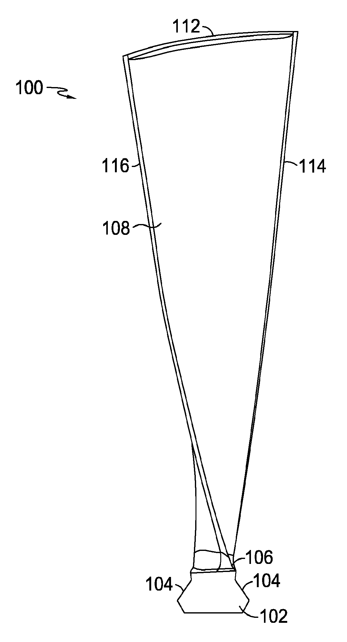
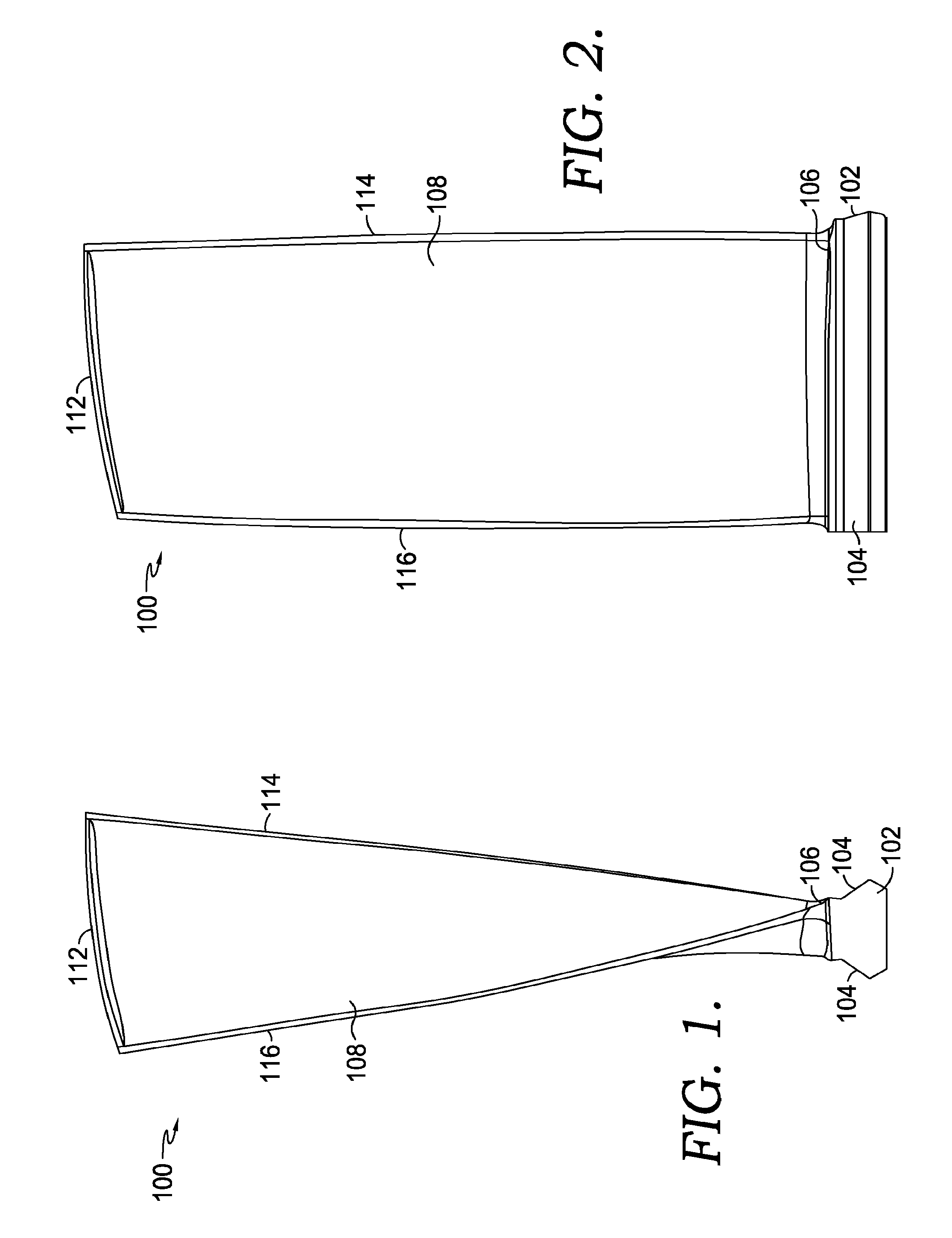
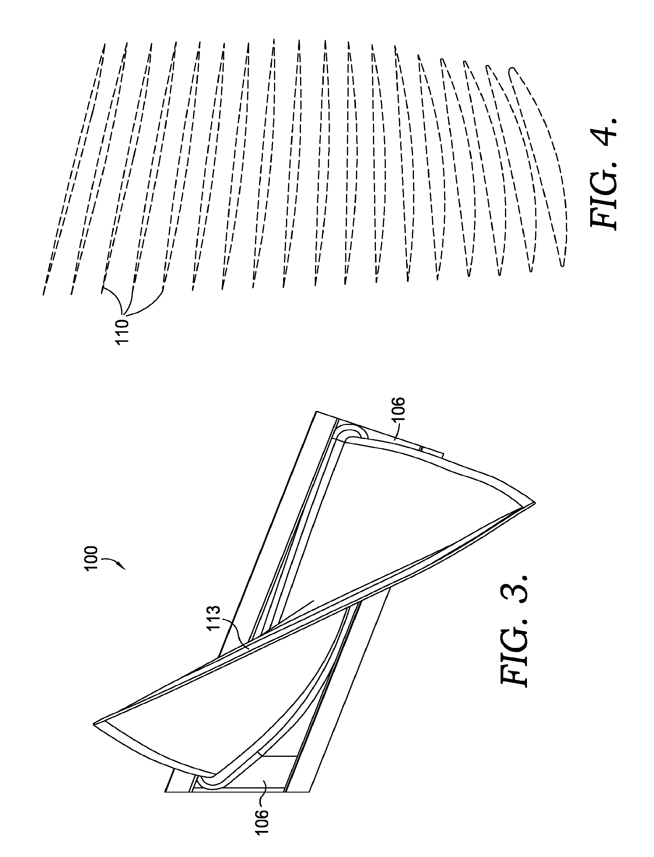
[0022]Referring initially to FIGS. 1-3, a compressor blade 100 is shown in accordance with an embodiment of the present invention. The compressor blade 100 comprises an attachment 102, which can also be referred to as a root. The attachment 102 utilizes one or more attachment surfaces 104 that are oriented so as to correspond with a slot in a compressor disk (not depicted) having a matching profile. Such an engagement maintains the blade within the disk, preventing it from moving ra...


PUM


Abstract

A compressor component having an airfoil with a profile in accordance with Table 1 is disclosed. The compressor component, such as a compressor blade, has an increased thickness over a portion of the airfoil span in order to increase stiffness. Furthermore, the airfoil has been restacked so as to induce a compressive stress in the blade root/attachment area. The increased stiffness and restacked airfoil combine to improve high-cycle fatigue capability of the compressor component.

Description

CROSS-REFERENCE TO RELATED APPLICATIONS[0001]None.TECHNICAL FIELD[0002]The present invention generally relates to a compressor component having an improved airfoil profile and tip geometry, known as a squealer tip, that addresses vibratory issues and high stress experienced in the airfoil leading edge region while also increasing rub tolerance at the tip.BACKGROUND OF THE INVENTION[0003]Compressor components having an airfoil, such as a compressor blade, are held within a rotating disk or shaft and are designed to rotate at a high rate of speed in order to compress a fluid passing through, such as air. A compressor typically comprises a plurality of stages, or rotating disks of blades, of diminishing diameter that raise the pressure and temperature, of the working fluid at each stage to a pre-determined level at the compressor exit.[0004]Axial compressors having multiple stages are commonly used in gas turbine engines for increasing the pressure and temperature of air to a pre-deter...

Claims


Application Information

Patent Timeline
IPC IPC(8): F01D5/14F01D9/02
CPCF01D5/141F04D29/324Y02T50/673F05D2260/94Y02T50/671F05D2250/74Y02T50/60F01D5/12
Inventor MILLER, EDWARD LENDAY, WILLIAM DAVIDPATEL, HITESH NARENDRATAYLOR, JEFFREY S.
Owner ANSALDO ENERGIA SWITZERLAND AG
Why Eureka
Try Eureka