Method for fabricating a custom implant abutment

a technology for custom-designed dental implants and abutments, which is applied in the field of custom-designed dental implant abutments, can solve the problems of not having a method or a device that would facilitate, and achieve the effect of simplifying the manufacturing process and facilitating the precision milling of customized titanium implants

Inactive Publication Date: 2012-08-23
B & D DENTAL
View PDF0 Cites 53 Cited by
  • Summary
  • Abstract
  • Description
  • Claims
  • Application Information

AI Technical Summary

Benefits of technology

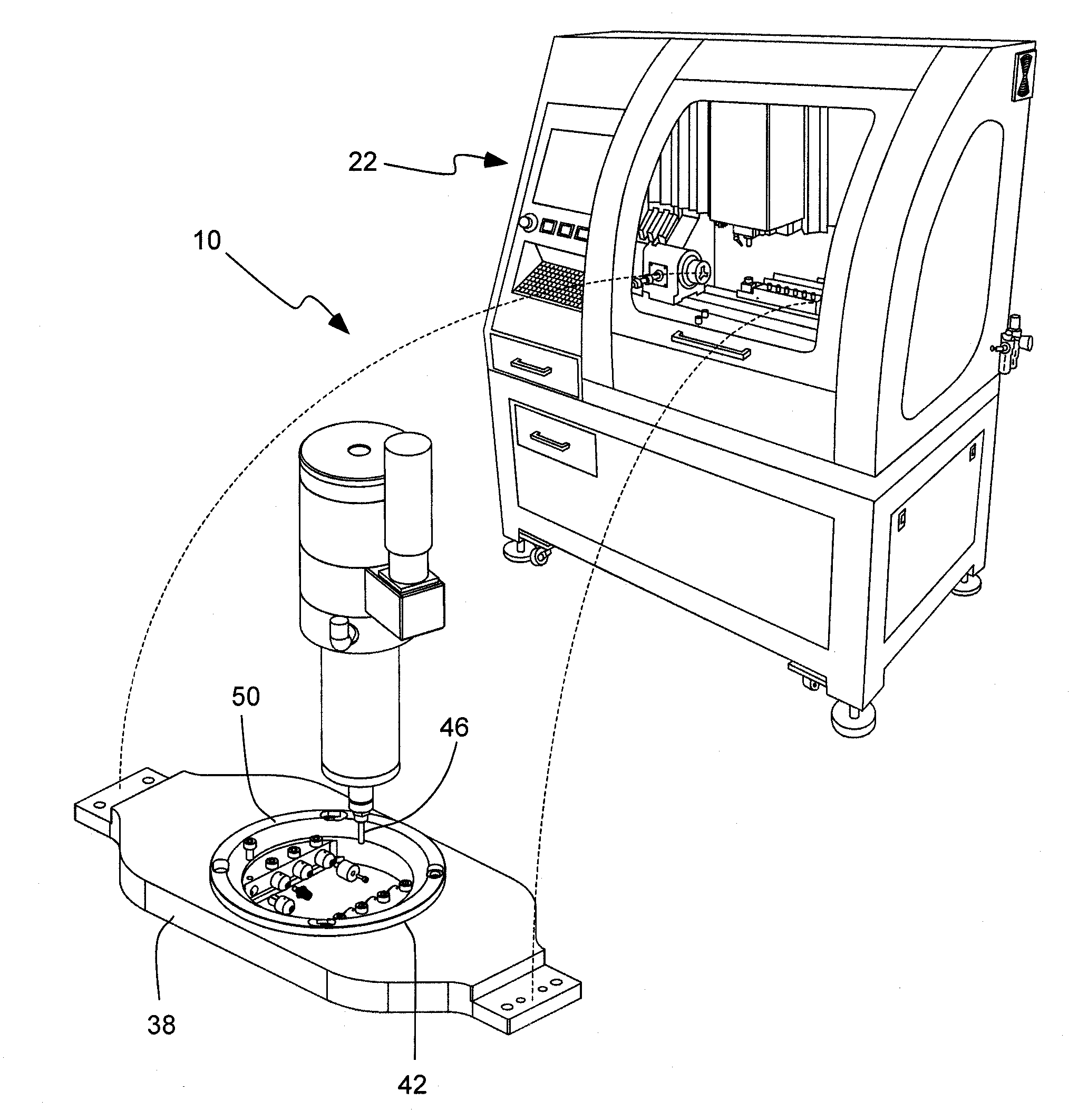
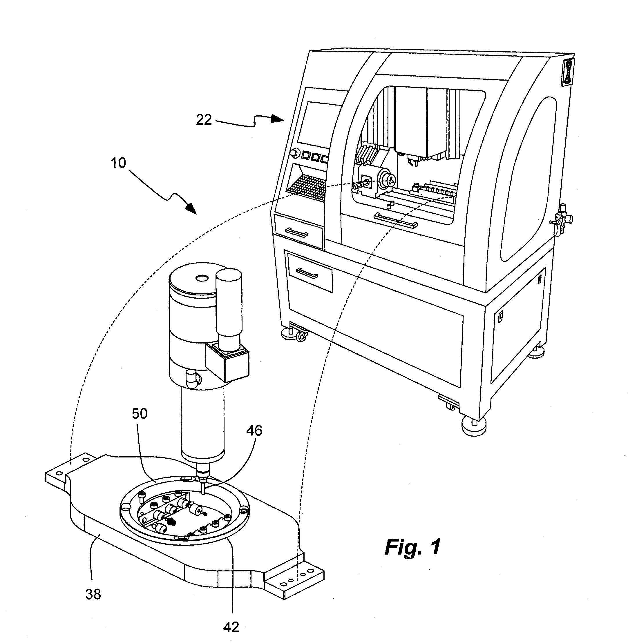
[0011]There has not been a method or device that would facilitate the precision milling of customized titanium implant abutments within a simplified manufacturing process that can be carried out in the typical dental laboratory or dental office. It has been recognized that it would be advantageous to develop a device, system and / or method for custom milling an implant abutment. In addition, it has been recognized that it would be advantageous to develop a device, system and / or method for milling an implant abutment and a dental prosthetic, such as a crown or coping, on the same milling machine.

Problems solved by technology

There has not been a method or device that would facilitate the precision milling of customized titanium implant abutments within a simplified manufacturing process that can be carried out in the typical dental laboratory or dental office.

Method used


Image

  • Method for fabricating a custom implant abutment
  • Method for fabricating a custom implant abutment
  • Method for fabricating a custom implant abutment

Examples


Embodiment Construction

)

Definitions

[0048]The term “implant” is used herein to refer to all types of dental implants that are affixed in a patient's mount, often to the bone of the jaw. Such implants can provide a structure to which an implant abutment is affixed via an interface geometry.

[0049]The term “implant abutment” is used herein to refer to all types of implant abutment structures affixed to the implant and between the implant and a crown or coping. The implant abutment can be a single, monolithic structure, or can be formed by more than one piece. The implant abutment has an interface geometry that matches and / or mates with the interface geometry of the implant.

[0050]The term “partial blank” is used herein to refer to a blank of material from which an implant abutment will be milled, machined or fabricated; but which has a prefabricated implant abutment interface geometry that mates with the implant, and a millable blank portion which will be formed into a body of the implant abutment.

[0051]The te...


PUM

PropertyMeasurementUnit
diameteraaaaaaaaaa
interface geometryaaaaaaaaaa
dimensional dental optical scannersaaaaaaaaaa

Abstract

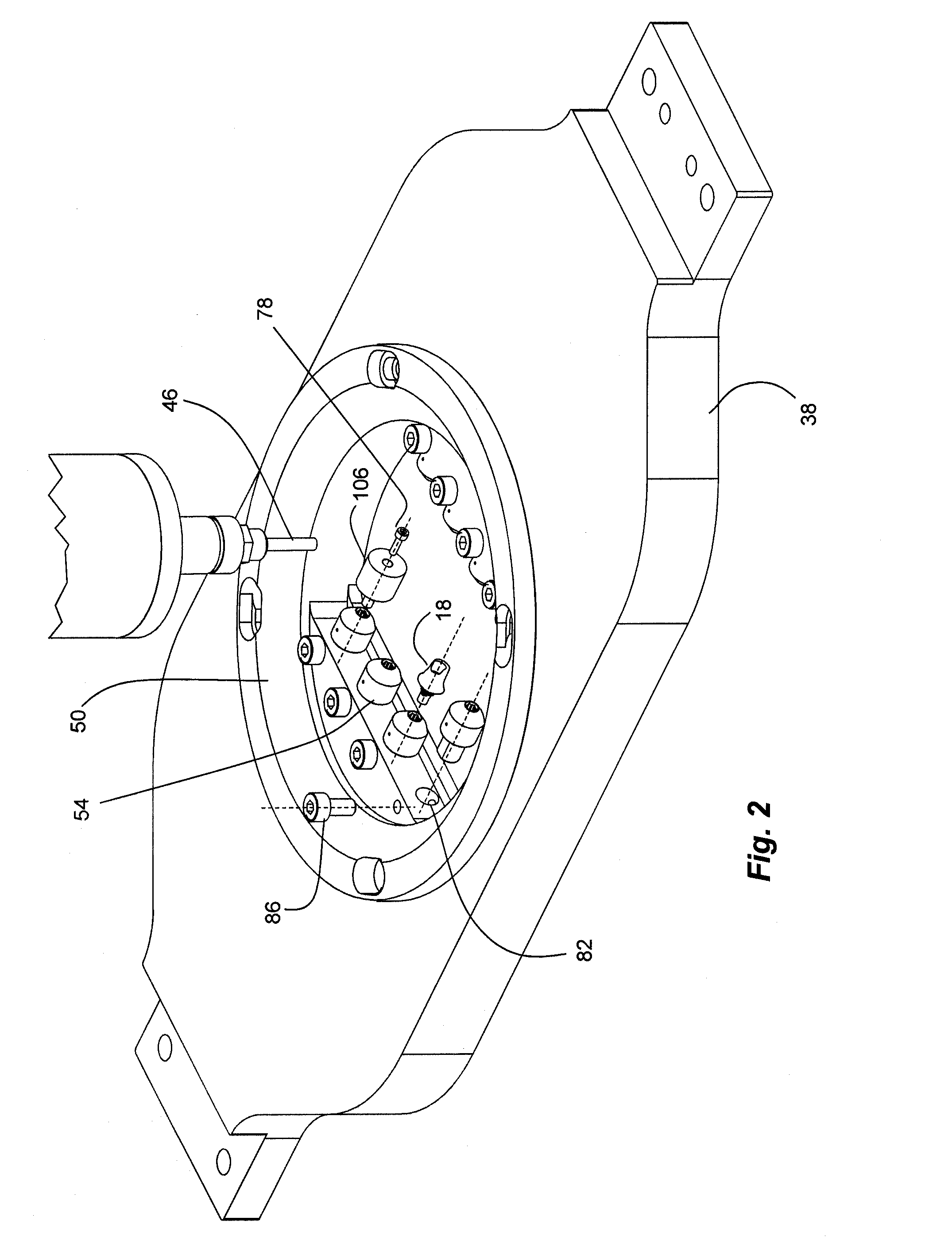
A system and method for fabricating custom implant abutments uses an implant abutment connector to secure a partial blank with respect to a milling tool of a CNC milling machine. The implant abutment connector has an implant interface geometry of an implant. The partial blank can have a prefabricated implant abutment interface geometry of the implant abutment; and can thus mate with the implant, and the implant interface geometry of the implant abutment connector.

Description

PRIORITY CLAIM / RELATED APPLICATION(S)[0001]This is related to U.S. patent application Ser. No. 12 / 431,543, filed Apr. 28, 2009; and U.S. patent application Ser. No. 12 / 431,568, filed Apr. 28, 2009; which are herein incorporated by reference in their entirety.BACKGROUND[0002]1. Field of the Invention[0003]The present invention relates generally to a method and a device for milling custom designed dental implant abutments.[0004]2. Related Art[0005]Computer Aided Design and Computer Aided Manufacturing (CAD / CAM) technology has had a big impact on the dental laboratory industry. Dental professionals can use these systems for designing a product and for controlling the manufacturing process. For example, once a dental prosthesis design has been produced with dental CAD software, CAM software controls the machines that construct the final product. The input information regarding the design of the dental prosthesis can either be created directly from the dentist's office based on a patient...

Claims


Application Information

Patent Timeline
Patent Type & Authority Applications(United States)
IPC IPC(8): A61C5/10A61C8/00B23Q11/00A61C5/77
CPCA61C8/005A61C8/0066A61C8/0068A61C8/0077Y10T409/303752A61C13/0006A61C13/0022A61C13/12A61C13/0004A61C17/22B23Q3/00A61C13/0003
Inventor JUNG, YUNOH
Owner B & D DENTAL
Why Eureka
Try Eureka