Energy storage system using supercritical air

a supercritical air and energy storage technology, applied in the direction of fluid couplings, lighting and heating apparatus, couplings, etc., can solve the problems of inability to recycle, unstable energy supply, and inability to meet the needs of large-scale production, and achieve high energy density, high efficiency, and the effect of high efficiency

Active Publication Date: 2012-08-30
INST OF ENGINEERING THERMOPHYSICS - CHINESE ACAD OF SCI
View PDF2 Cites 41 Cited by
  • Summary
  • Abstract
  • Description
  • Claims
  • Application Information

AI Technical Summary

Benefits of technology

[0058]There are several advantages of this invention, including high energy density, high efficiency, no need for big storage vessel and special geographical condi

Problems solved by technology

However, the demand for electricity varies considerably emergently, daily and seasonally, and the maximum demand may only last for a few hours each year which leads to inefficient, over-designed and expensive plants.
The penetration of renewable resources may displace significant amounts of energy produced by large conventional plant.
However, intermittency and non-controllability are inherent characteristics of renewable energy based electricity generation systems, which renders energy supply unstable, even unusable.
Such disadvantages have become major hurdles or obstacles to the extensive utility of the renewable energy sources, the green electricity industry.
However, more drastic load fluctuation and emergent voltage drop are anticipated in DER systems due to smaller capacity and higher possibility of line fault than the conventional power system.
However, only Pumped Hydro and Compressed Air Energy Storage have been commercially utilized currently in a large scale, in consideration of capacity, energy storage duration, energy density, charge-discharge efficiency, life time, operating cost and environmental effects.
How

Method used


Image

  • Energy storage system using supercritical air
  • Energy storage system using supercritical air
  • Energy storage system using supercritical air

Examples


first embodiment

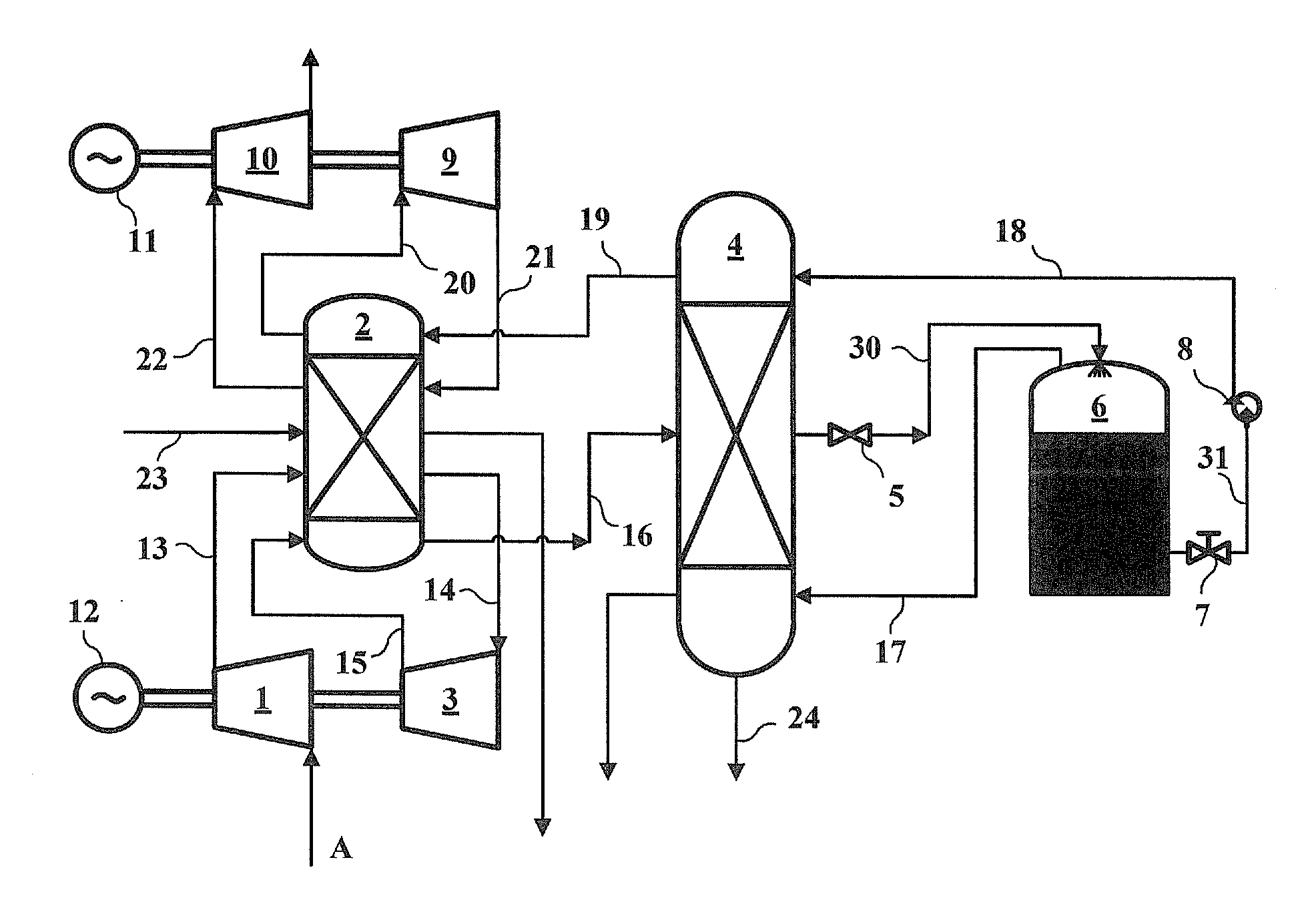
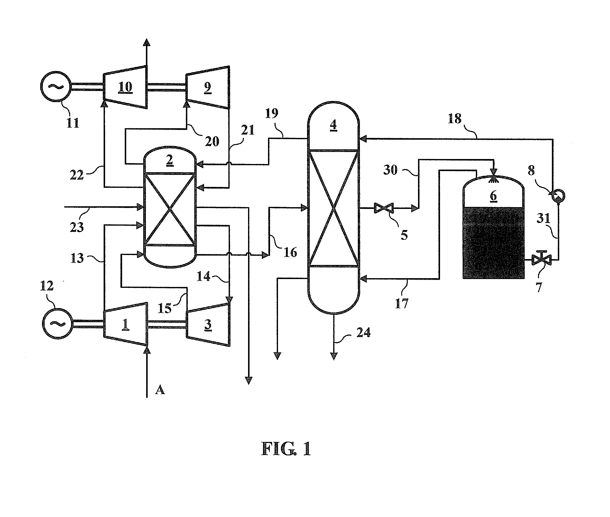
[0071]FIG. 1 shows the energy storage system using supercritical air. The system includes a low-pressure compressor 1, a heat exchanger and storage device 2, a high-pressure compressor 3, a cold exchanger and storage device 4, a throttle valve 5, a cryogenic tank 6, a valve 7, a cryogenic pump 8, a high pressure expander 9, a low-pressure expander 10, a generator 11, a drive unit 12 and air A. The system may further comprise a plurality of pipes, such as those denoted by 13, 14, 15, 16, 17, 18, 19, 20, 21, 22, 23, 24, 30 and 31.

[0072]In this example, the drive unit 12 is connected with the compressors 1 and 3 by a common transmission shaft, and the generator 11 is connected with the expanders 9 and 10 by a common transmission shaft. The low-pressure compressor 1 and high-pressure compressor 3 are connected to the heat exchanger and storage device 2 by the pipes 13 and 14, 15, respectively. The air A flows into the system at an inlet of low-pressure compressor 1. The heat exchanger a...

fourth embodiment

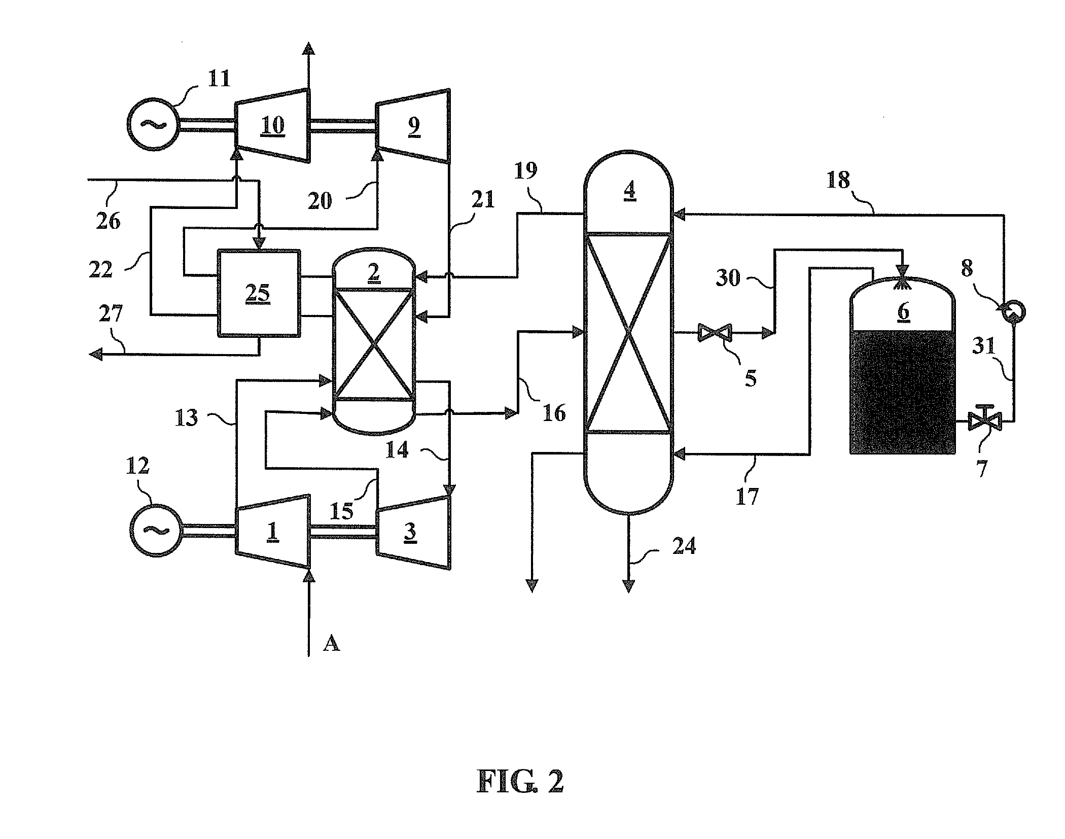
[0083]In the fourth embodiment, the wind energy is directly used to drive the compressors and is not needed to be converted into electricity. The different streams of compressed air are transferred to the heat exchanger and storage device 2 via pipes respectively so as to store compression heat therein. As the compression occurs in different stages and different places, a portion of the compression heat is dissipated during the transferring of working air. External heat resource, such as waste heat and residual heat, can be added into the energy storage system via pipe 2 or additional heat can be added to the heat exchanger and storage device 2 through heating by use of off-peak electricity C.


PUM


Abstract

Disclosed is an energy storage system using supercritical air, comprising compressor units (1, 3), heat exchanger and storage device (2, 4), a throttle valve (5), a cryogenic tank (6), a cryogenic pump (8), expander units (9, 10), a generator (11), a driver unit (12), and a plurality of pipes. There are several advantages of this invention, including high energy density, high efficiency, no storage cycle and geographical conditions restriction, easy implementation with all kinds of power stations, environment friendliness and capability of recycling low to medium temperature waste heat and so on.

Description

TECHNICAL FIELD[0001]The present invention in general relates to energy storage, and in particular, to an electrical energy storage system using supercritical air.BACKGROUND[0002]Electrical energy storage systems (EES) are urgently needed by the conventional electricity generation industry. Unlike any other successful commodities markets, the conventional electricity generation industries have little or no storage component. The electricity transmission and distribution systems are operated for the simple one-way transportation from remote and large power plants to consumers. This means that electricity should always be consumed precisely as it is produced. However, the demand for electricity varies considerably emergently, daily and seasonally, and the maximum demand may only last for a few hours each year which leads to inefficient, over-designed and expensive plants. EES allows energy production to be de-coupled from its supply, self generated or purchased. By having large-scale ...

Claims


Application Information

Patent Timeline
IPC IPC(8): F15B1/027
CPCF03G7/06F25J3/04842F25J1/0012F25J1/0037F25J1/0045F25J1/0228F25J1/0251F25J3/04018F25J3/04054F25J3/04084F25J3/04187F25J3/04193F25J3/04309F25J3/044F25J3/04581F25J2205/24F25J2230/04F25J2230/08F25J2230/30F25J2240/10F25J2240/90F25J2245/90F01K7/22F01K5/02F25J2235/02Y02E60/16F01K3/004
Inventor CHEN, HAISHENGTAN, CHUNQINGLIU, JIAXU, YUJIE
Owner INST OF ENGINEERING THERMOPHYSICS - CHINESE ACAD OF SCI
Why Eureka
Try Eureka