
Microfluidic mixer, method for mixing fluids

Inactive Publication Date: 2012-08-30
UCHICAGO ARGONNE LLC
View PDF8 Cites 20 Cited by
  • Summary
  • Abstract
  • Description
  • Claims
  • Application Information

AI Technical Summary

Benefits of technology

[0017]Another object of the invention is to provide a device to enable thorough mixing of fluids, which in the case of liquids, comprise a total volume of as little as 1×10⁻¹⁵ liters. The fluids can be either charged or uncharged. A feature of the invention is a mixing chamber having varying depths and widths. The varying widths provide a means for inducing lateral flow. An advantage of the invention is a means for imparting lateral velocities to the fluid, thereby enhancing mixing. Another advantage is that varying widths and depths provides a predetermined constant pressure drop across the length of the fluid conduit. This predetermined pressure drop feature (either identical along each of the various segments of the conduit, or not-identical along the segments) provides a means for preventing clogging or fluid build-up at constricting points along the channels. The devices can accommodate fluid volumes from a few sub pico liters to more than 100 microliters.

Problems solved by technology

At macroscopic fluid volumes, e.g., greater than 1 milliliter, turbulence is generated easily such that mixing occurs rapidly.
As a result, mixing does not occur, at least not sufficiently compared to the mixing seen at the macroscopic scale.
This means that chaotic flow patterns, which would be used at larger scales to induce mixing, cannot be created.
However, these configurations rely on intersecting flows, making them more difficult to scale down to true micro-fluidic volume processing.
However, these systems have narrow channels which clog easily and which do not scale well to accommodate smaller mixture volumes.
Rather, such counterflow systems experience high pressure drops.
This leads to bottlenecks, with the fluids not passing through the channel.
This leads to bulkiness of the final configuration.

Method used


Image

  • Microfluidic mixer, method for mixing fluids
  • Microfluidic mixer, method for mixing fluids
  • Microfluidic mixer, method for mixing fluids

Examples


example 1

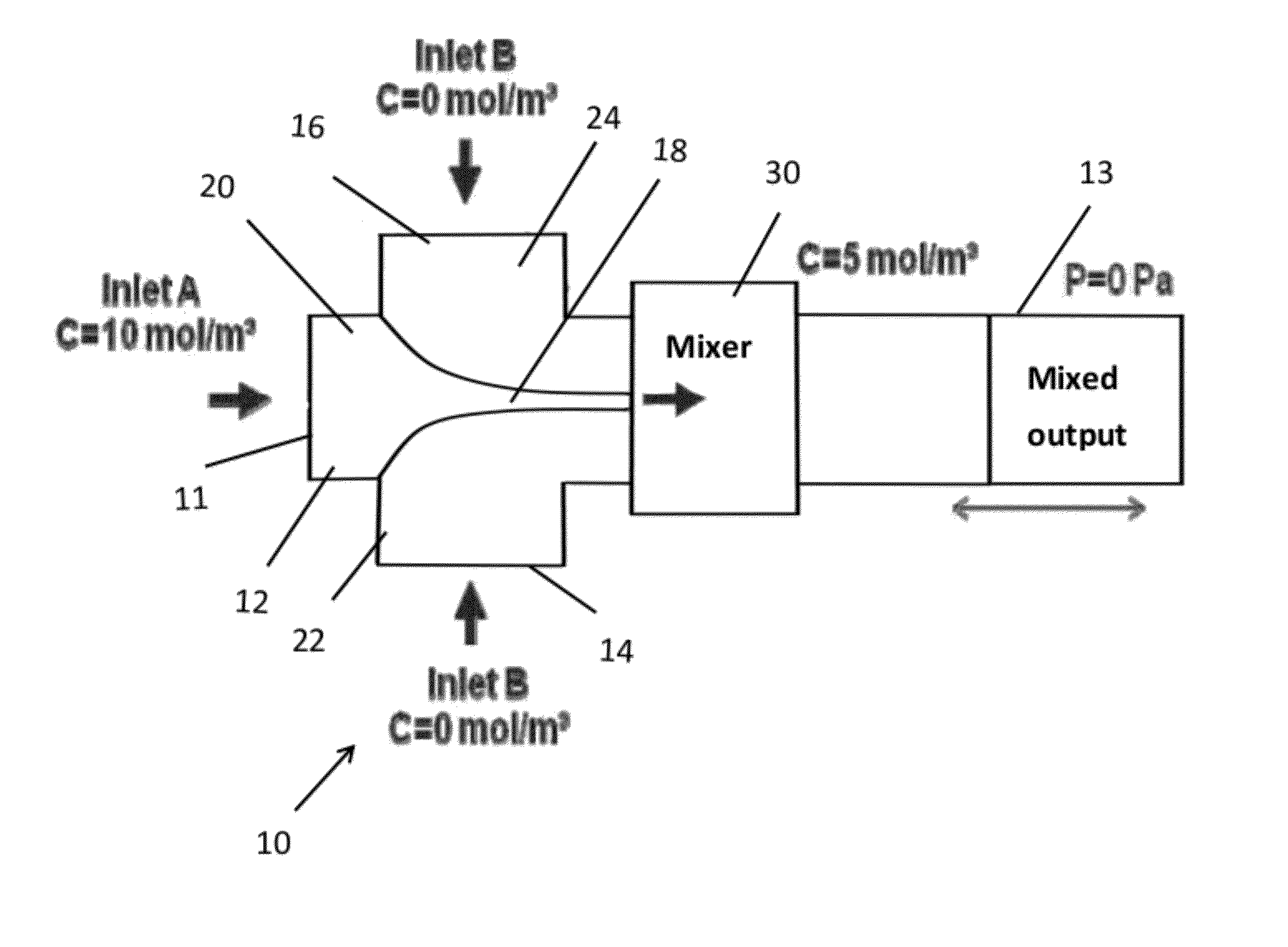
[0043]Simulations were run in Comsol Multiphysics™ (Comsul, Inc., Burlington, Mass.) using the Microfluidic Incompressible Navier-Stokes and Convection Diffusion models. The geometries were drawn in Comsol to match the same depth and width parameters of the T-junction and mixer. Suitable parameters include a fluid of density of about 1000 kg / m3 (e.g. 998 kg / m3 was used in the modeling), viscosities of between about 5×10⁻⁴ Pa·s and 1 mPa·s (e.g. 8×10⁻⁴ Pa s and 1.002 Pa s) were used in the modeling) and an isotropic diffusivity coefficient of about 10−10 m2 / s. Suitable inlet boundary conditions are about 1 mm / s and 5 mm / s (e.g. 1.1 mm / s was used for the modeling) with a concentration of about 10 mol / m3 for the center flow; about 1 mm / s with a concentration of about 0 mol / m3 for the sheath flows for component A.

[0044]In this embodiment, the fluid dynamics are periodic such that the pressure drops are substantially the same throughout the length of fluid travel through the device. FIG....


PUM


Abstract

The invention provides a fluid mixer comprising a substrate defining channels having varying widths and depths, wherein the channels have a total mixing distance of from about 50 microns to 1 millimeter. Also provided is a method for mixing fluids, the method comprising: directing a plurality of fluids to a mixing channel having a first width and a first depth; redirecting the directed plurality of fluids to a mixing channel having a second width smaller than the first width and having a second depth greater than the first depth; and repeating the process.

Description

PRIORITY[0001]This utility application claims the benefits of U.S. Provisional Application No. 61 / 447,576, filed on Feb. 28, 2011.CONTRACTUAL ORIGIN OF THE INVENTION[0002]The United States Government has rights in this invention pursuant to Contract No. DE-AC02-06CH11357 between the United States Government and UChicago Argonne, LLC representing Argonne National Laboratory.BACKGROUND OF THE INVENTION[0003]1. Field of the Invention[0004]This invention relates to a method and device to facilitate mixture of fluids, and more particularly, this invention relates to a passive method and device for facilitating mixture of liquids having volumes as little as 1×10⁻⁹ microliters.[0005]2. Background of the Invention[0006]At macroscopic fluid volumes, e.g., greater than 1 milliliter, turbulence is generated easily such that mixing occurs rapidly. This is readily discernable by the naked eye.[0007]Since the advent of the first lab on a chip in the 1980s, microfluidics research has been at the f...

Claims


Application Information

Patent Timeline
IPC IPC(8): B01F5/06B81B1/00
CPCB01F5/0655B01F13/0062B01F2215/0468B01F2215/045B01F2215/0431B01F25/4338B01F33/3011
Inventor OCOLA, LEONIDAS E.JOSHI-IMRE, ALEXANDRAPALACIOS, EDGAR
Owner UCHICAGO ARGONNE LLC
Learn More