
Thermally adjustable surgical tool, balloon catheters and sculpting of biologic materials

a surgical tool and adjustable technology, applied in the field of surgical tools, can solve problems such as inductive heating of ferromagnetic coatings, and achieve the effect of consistent temperatur

Active Publication Date: 2012-09-06
DOMAIN SURGICAL
View PDF5 Cites 30 Cited by
  • Summary
  • Abstract
  • Description
  • Claims
  • Application Information

AI Technical Summary

Benefits of technology

[0017]According to one aspect of the invention, a thermal surgical tool system is provided with a ferromagnetic coating over a conductor and an oscillating electrical energy source for generating heat at the location of the coating. The oscillating electrical energy may cause inductive heating of the ferromagnetic coating. Moreover, the surgeon may be able to quickly turn the surgical or therapeutic tool on and off due to a small heat latency. This may provide the advantage of allowing the surgeon to rapidly deliver a thermal effect only at desired locations, which may also prevent the accidental delivery of undesired thermal effects while waiting for the tool to cool.
[0023]According to another aspect of the invention, a thermal system may be used to sculpt portions of biological material. For example, a herniated spinal disc may be sculpted such that the herniated portion is removed so that the disc remains within the spinal column Likewise, biological material, such as cartilage may be smoothed to repair damage and / or to prevent further damage of an uneven surface. Furthermore, a thermal tool may be used to reduce plaque formations in blood vessels or to smooth ducts to thereby improve flow there through. Moreover, tissue may be thermally treated to reduce size and / or allow for easier removal of the tissue, such as, for example, reducing the size of stones in a gall bladder prior to removal from a small incision.

Problems solved by technology

The oscillating electrical energy may cause inductive heating of the ferromagnetic coating.

Method used


Image

  • Thermally adjustable surgical tool, balloon catheters and sculpting of biologic materials
  • Thermally adjustable surgical tool, balloon catheters and sculpting of biologic materials
  • Thermally adjustable surgical tool, balloon catheters and sculpting of biologic materials

Examples


Embodiment Construction

[0092]The invention and accompanying drawings will now be discussed in reference to the numerals provided therein so as to enable one skilled in the art to practice the present invention. The drawings and descriptions are exemplary of various aspects of the invention and are not intended to narrow the scope of the appended claims.

[0093]As used herein, the term “ferromagnetic,”“ferromagnet,” and “ferromagnetism” refers to any ferromagnetic-like material that is capable of producing heat due to magnetic induction, including but not limited to ferromagnets and ferrimagnets. It is not intended that such materials must be heated exclusively due to magnetic induction and such may acquire heat from resistive loses, including the skin effect due to eddy currents, in addition to magnetic induction.

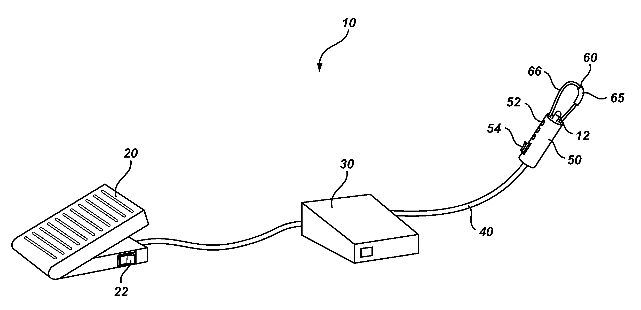
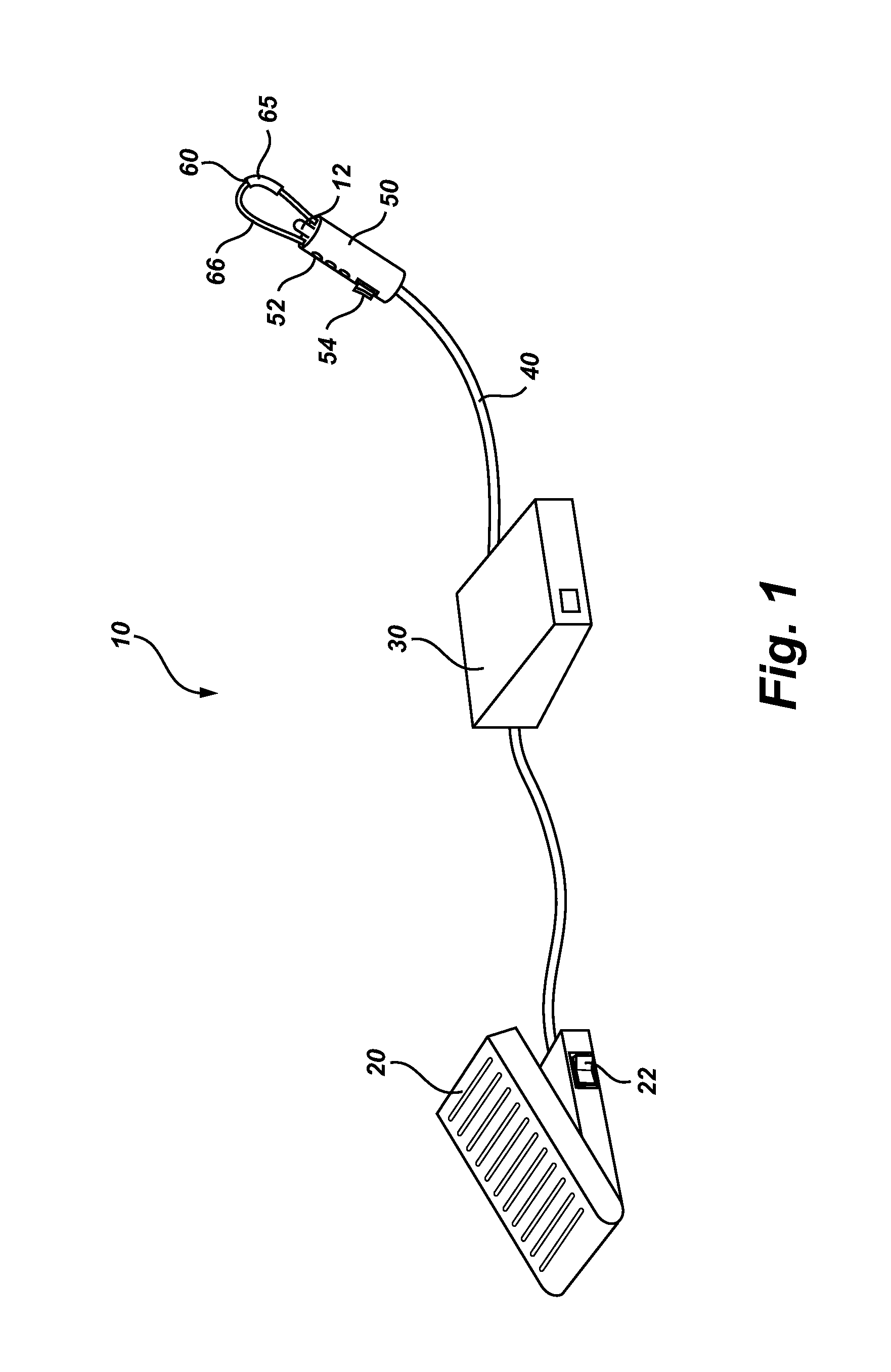
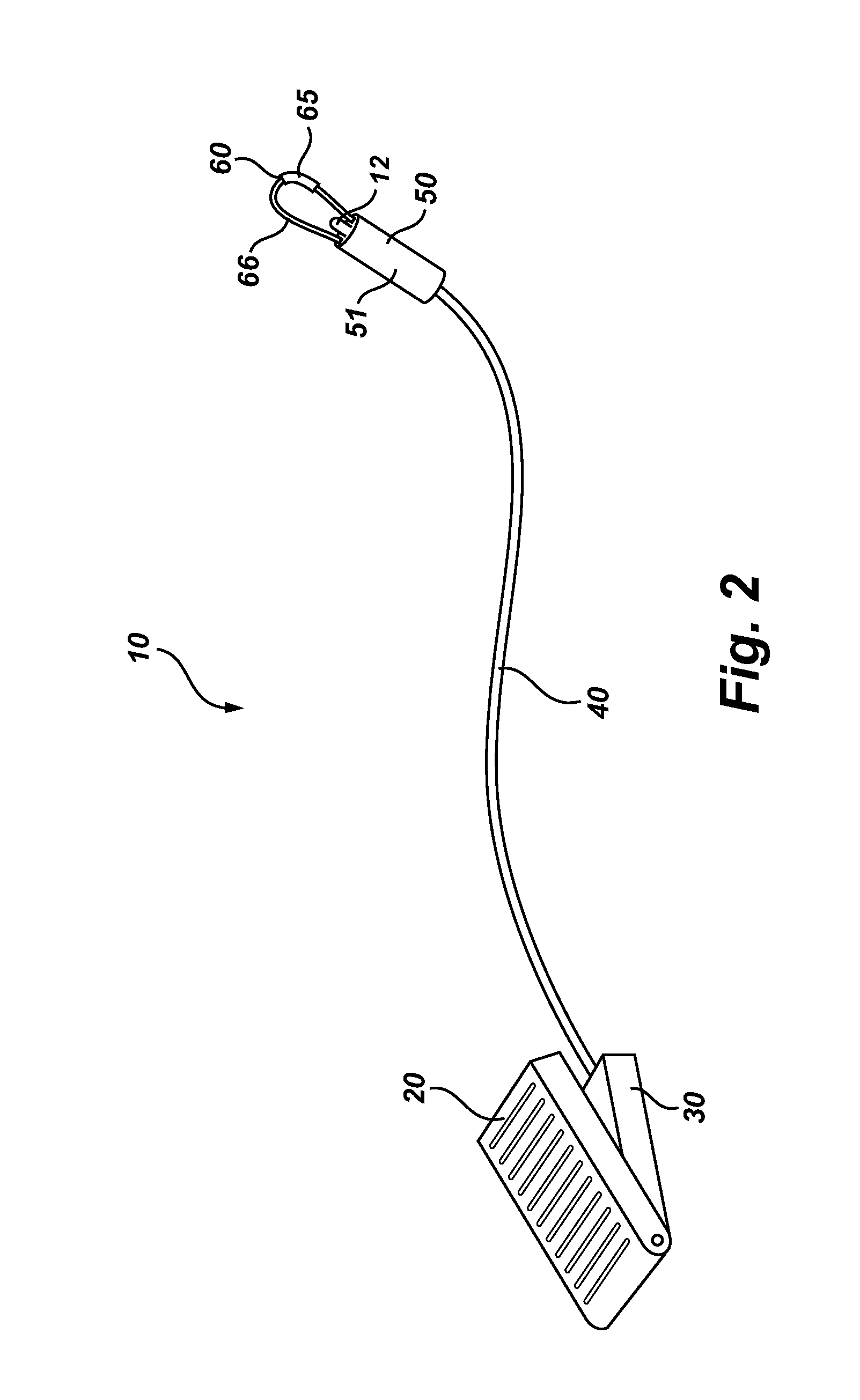
[0094]Turning now to FIG. 1, there is shown a perspective view of a thermal surgical tool system, generally indicated at 10. As will be discussed in additional detail below, the thermal tool system...


PUM

PropertyMeasurementUnit
Temperatureaaaaaaaaaa
Flow rateaaaaaaaaaa
Surfaceaaaaaaaaaa

Abstract

Thermally adjustable surgical tools include a conductor and a ferromagnetic material. The ferromagnetic material may be quickly heated when subjected to high frequency alternating current through the conductor. The ferromagnetic material may also cool rapidly because of its relatively low mass and the small thermal mass of the conductor. The thermally adjustable surgical tools may be used to sculpt, melt, break and / or remove biological material. The thermally adjustable surgical tools may also include balloon catheters which can heat fluid to thereby treat biological material.

Description

RELATED APPLICATIONS[0001]The present application is a continuation-in-part of U.S. patent application Ser. No. 12 / 647,358, filed Dec. 24, 2009, which claims the benefit of U.S. Provisional Patent Application Ser. No. 61 / 170,203, filed Apr. 17, 2009, U.S. Provisional Patent Application Ser. No. 61 / 170,220, filed Apr. 17, 2009, and U.S. Provisional Patent Application Ser. No. 61 / 170,207, filed Apr. 17, 2009, each of which are incorporated hereby by references in their entirety. The present application also claims the benefit of U.S. Provisional Application Ser. No. 61 / 380,179, filed on Sep. 3, 2010, and U.S. Provisional Application Ser. No. 61 / 473,715, filed on Apr. 8, 2011, which are each incorporated herein by reference in their entirety.BACKGROUND OF THE INVENTION[0002]1. The Field of the Invention[0003]The present invention relates to surgical tools. More specifically, the present invention relates to thermally adjustable surgical tools used in open and minimally invasive surgica...

Claims


Application Information

Patent Timeline
IPC IPC(8): A61B18/14A61B18/04
CPCA61B18/082A61B2218/001A61B2018/00107A61B2018/00642A61M25/00A61B18/1442A61M25/0045A61M25/10A61B2018/00148A61B2018/0041A61B2018/00559A61B2018/00577A61B2018/00601A61B2018/0063A61B2018/00702A61B2018/00815A61B2018/00821A61B2018/00982A61B2018/046A61B2018/141A61B18/10
Inventor MANWARING, KIMMCNALLY, DAVID
Owner DOMAIN SURGICAL
Learn More