
System for charging electric vehicle batteries from street lights and parking meters

a technology for charging electric vehicles and street lights, applied in the direction of batteries/cells, battery/fuel cell control arrangements, instruments, etc., can solve the problems of rapid increase in the number of public charging stations available to electric vehicle users, city governments and vehicle users alik

Inactive Publication Date: 2012-09-13
CHAPIN WILLIAM L MR
View PDF10 Cites 172 Cited by
  • Summary
  • Abstract
  • Description
  • Claims
  • Application Information

AI Technical Summary

Benefits of technology

[0010]Another object of the invention is to provide a system for charging batteries of electric vehicles which includes an accessory power interface module that is readily retro-fittable to an existing street light, parking meter or other such fixture which is supplied with electrical power from municipal power grid mains, to thus enable the fixture to function as an electric vehicle battery charging station while still performing its original intended function such as illuminating a street or receiving parking fees.
[0030]According to the invention, the On-Board Charge Control System mounted in a vehicle includes a safety interlock mechanism to prevent electrical power from being supplied to the vehicle traction motor while the vehicle charging plug is inserted into the charging station street receptacle. In a preferred embodiment, the safety interlock mechanism is implemented by a vehicle Drive Enable module connected in series with the vehicle battery and traction motor controller. The vehicle Drive Enable module prevents current from flowing to the vehicle drive motor unless the plug at the end of the vehicle charger cable is removed from the street charging station receptacle and inserted into a similarly constructed receptacle on the Charging Current Controller Module, which provides an enabling signal to the Drive Enable module only when the plug is inserted into the receptacle of the Charging Current Controller Module.
[0032]The electric vehicle charging system according to the present invention may optionally include an enhancement such as an additional electronic interlock relay located with the power outlet receptacle, which requires the presence of correctly coded RFID chip in the plug at the end o the vehicle charger cable, to enable current to flow to the plug. Also, the receptacle may optionally include an obstructing security cover plate which covers the entrance opening to the receptacle against rain, snow and the like, and further secures the receptacle against being tampered with or subjected to unauthorized use. In this embodiment, the security cover plate is operable by an electro-mechanical actuator such as an electric motor or solenoid within the receptacle, which is energized by electronic sensing and control circuitry only when a correctly coded mechanical, magnetic or electronic key such as an RFID chip is presented to the receptacle.

Problems solved by technology

As the number of electric vehicles in regular use increases, problems faced by city governments and vehicle users alike because of an insufficient number of public charging stations available to the users of electric vehicles are rapidly increasing.

Method used


Image

  • System for charging electric vehicle batteries from street lights and parking meters
  • System for charging electric vehicle batteries from street lights and parking meters
  • System for charging electric vehicle batteries from street lights and parking meters

Examples


Embodiment Construction

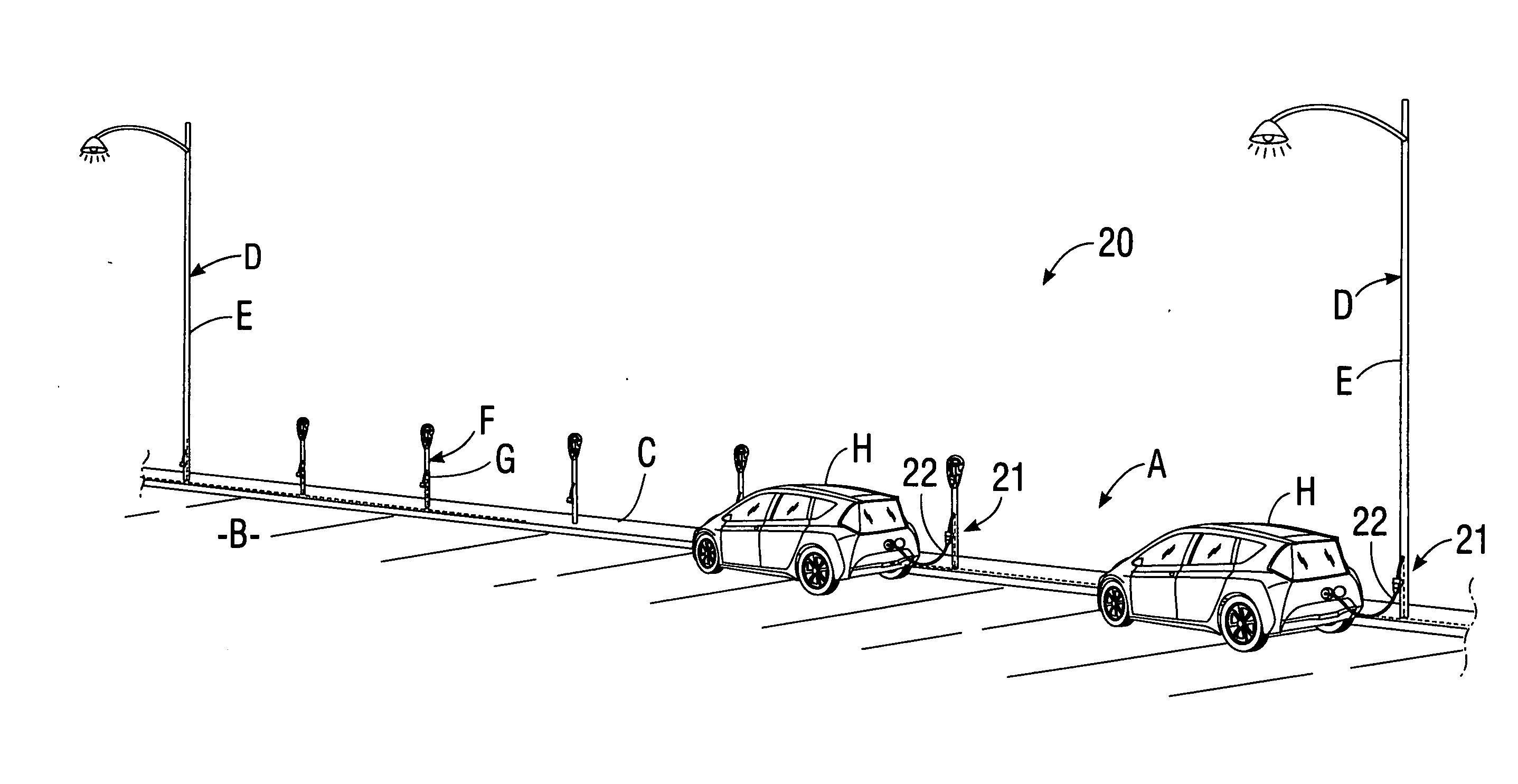
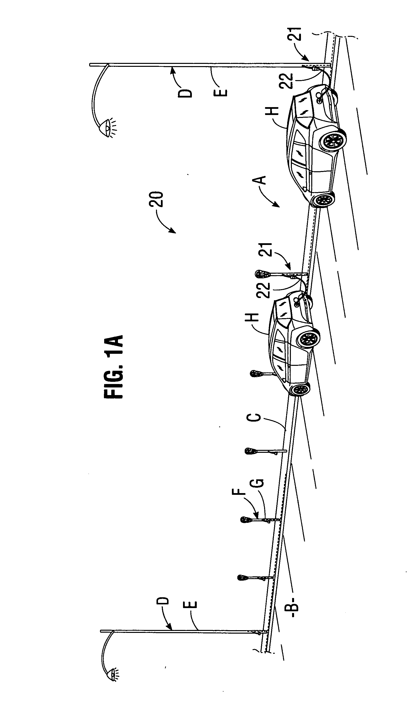
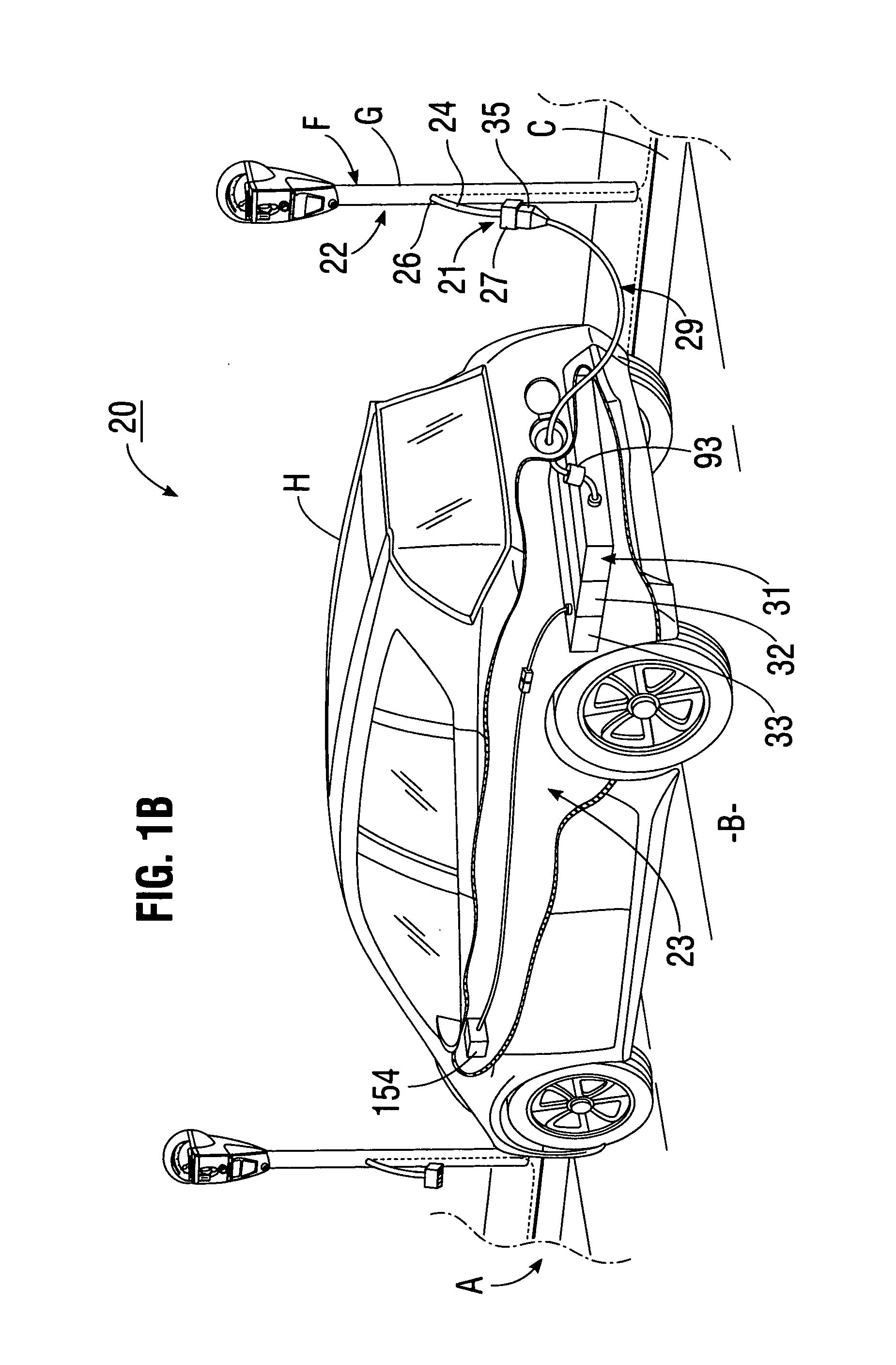
[0048]FIGS. 1-12 illustrate a system for charging electric vehicle batteries from street lights and parking meters according to the present invention.

[0049]Referring first to FIG. 1A, a street or road A is shown which includes a roadway B, a curb C, street lights D having standards E, and parking meters F having standards G located adjacent to the curb. Referring to FIGS. 1A and 1B, it may be seen that a Charging System 20 for charging batteries of electric vehicles H includes a retrofit or modification apparatus 21, for converting street lights D and / or parking meters F into dual function fixtures which function as Charging Stations 22 for electric vehicles in addition to their original functions of illuminating a street or receiving parking fees.

[0050]As may be seen best by referring to FIG. 1B in addition to FIG. 1A, system 20 for charging batteries of electric vehicles includes in addition to Charging Station 22 an On-Board Charge Control System 23 installed in electric vehicle ...


PUM


Abstract

A system for charging batteries of electric vehicles from public fixtures such as street lights and parking meters includes modifying the fixture to convert it to a vehicle battery charging station using a power interface module having a novel keyed electrical power output receptacle connectable to power mains powering the fixture. The system includes a complementarily coded, keyed plug which must be inserted into the power output receptacle to access electrical power from the receptacle, the plug being located at the input end of vehicle charger cable terminated at output end thereof by a vehicle-mounted charge control system which will actuate a charging current contactor permitting charging current to flow from the receptacle to batteries within the vehicle only if a pre-paid charge authorization payment device, such as a magnetically or electronically encoded charge card is inserted into a charger station access enable device such as card reader mounted in the vehicle.

Description

BACKGROUND OF THE INVENTION[0001]A. Field of the Invention[0002]The present invention relates to methods and apparatus for charging batteries of all-electric and hybrid vehicles. More particularly, the invention relates to a novel system comprised of a method and apparatus which utilize existing electrical power supplied to municipal street lights, parking meters and the like, to charge vehicle batteries, and which relegates paying for charging power to a vehicle mounted apparatus.[0003]B. Description of Background Art[0004]Air pollution resulting from increasing numbers of vehicles powered by internal combustion engines has prompted people worldwide to utilize alternative vehicles. The latter include all-electric vehicles which utilize electric traction motors powered by “on-board” batteries mounted in the vehicle. Hybrid vehicles also use electric motors powered by on-board batteries as a prime mover, but have a small, low-power, low-pollution internal combustion engine which may ...

Claims


Application Information

Patent Timeline
Patent Type & Authority Applications(United States)
IPC IPC(8): H02J7/00
CPCB60L11/1818G07F15/005B60L11/1825B60L11/1846B60L11/1848B60L11/1868B60L11/1877B60L2210/30B60L2230/12B60L2230/16B60L2250/12B60L2250/16B60L2250/20Y02T10/7005Y02T90/121Y02T10/7088Y02T10/7241Y02T10/7066Y02T90/163Y02T90/169Y02T90/14Y02T90/128Y02T90/127Y04S30/14B60L11/1824B60L53/16B60L53/31B60L53/65B60L53/665B60L58/20B60L50/66B60L53/18B60L53/305B60L53/34Y02T10/70Y02T10/7072Y02T10/72Y02T90/12Y02T90/167Y02T90/16
Inventor LAU, DAVID M. K.
Owner CHAPIN WILLIAM L MR
Learn More