P-type isolation between qcl regions

Active Publication Date: 2012-09-20
THORLABS QUANTUM ELECTRONICS
View PDF1 Cites 25 Cited by
  • Summary
  • Abstract
  • Description
  • Claims
  • Application Information

AI Technical Summary

Benefits of technology

[0008]In accordance with other embodiments of the present disclosure, laser structures are also contemplated where isolation regions are solely pr

Problems solved by technology

These p-type layers are typically not very conductive.
Accordingly, electron diffusion from one area to an adjacent area above the active core ca

Method used


Image

  • P-type isolation between qcl regions
  • P-type isolation between qcl regions
  • P-type isolation between qcl regions

Examples


Example

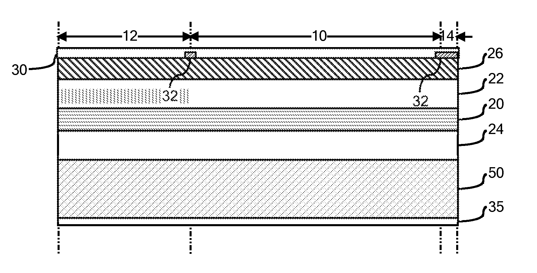
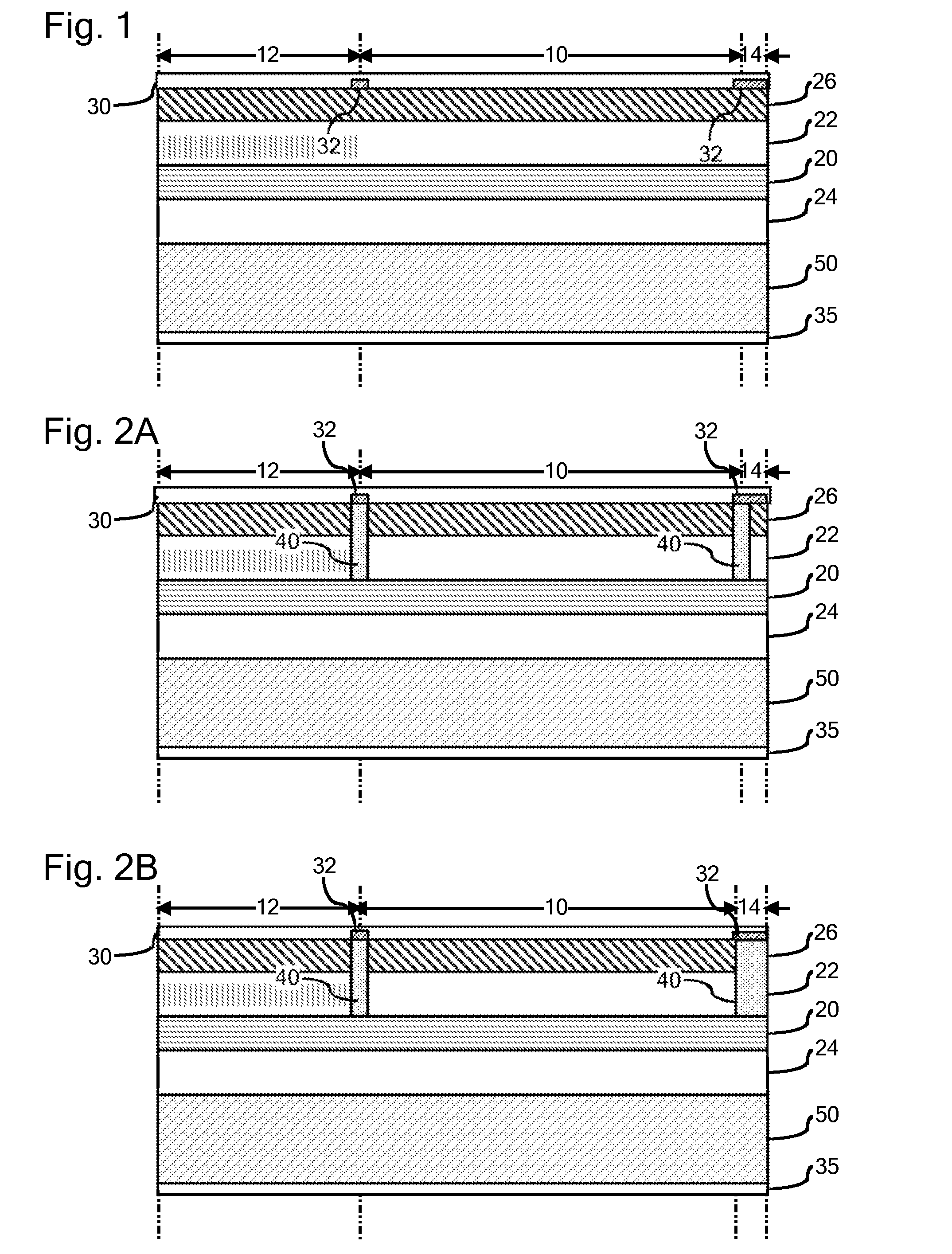
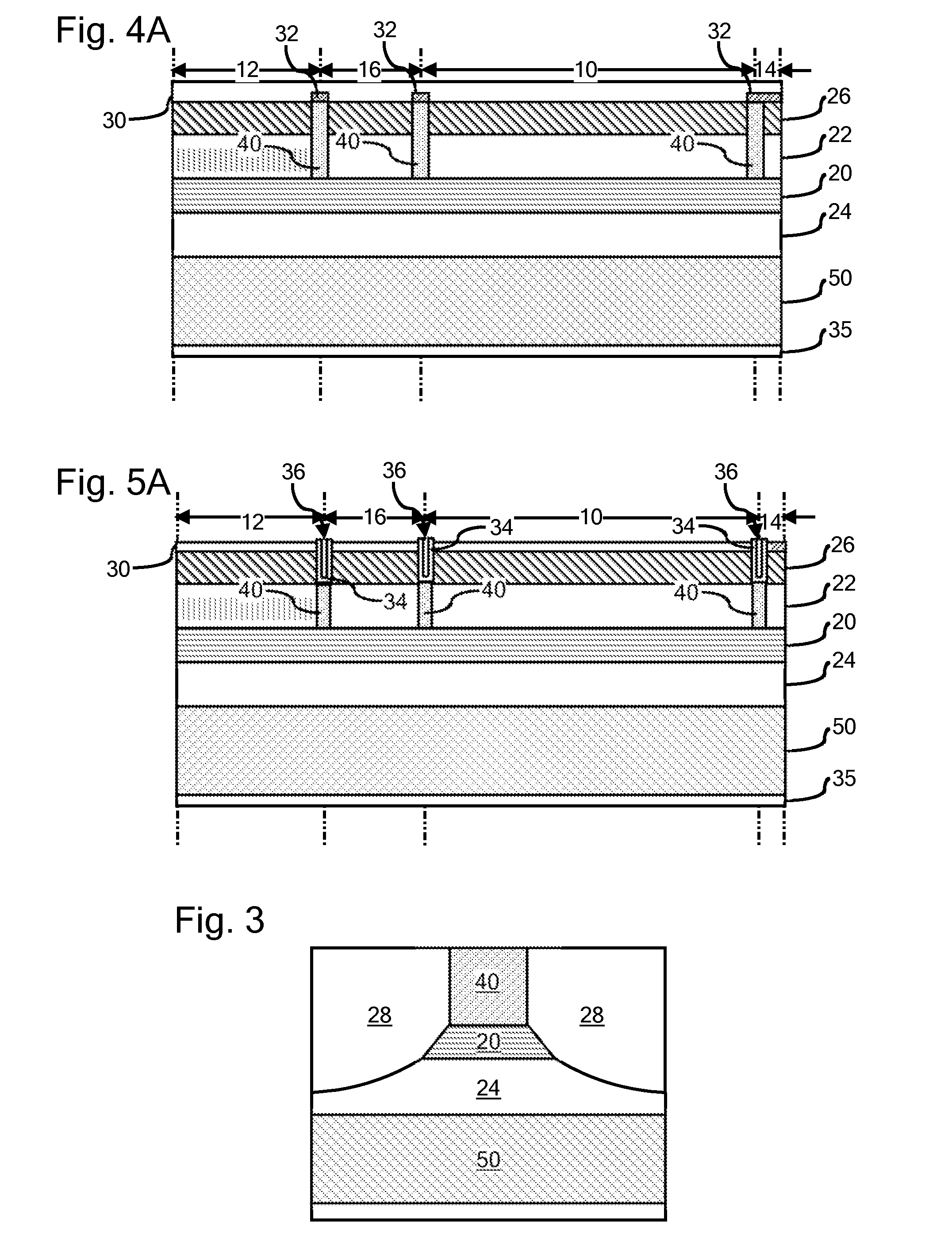
[0017]Although the concepts of the present disclosure enjoy applicability to any type of multi-section QCL, specific embodiments of the present disclosure are illustrated herein with reference to DBR quantum cascade lasers. Nevertheless, the present disclosure and accompanying claims should not be limited to DBR lasers or to the specific materials mentioned in the present description, unless otherwise expressly noted. For example, and not by way of limitation, FIG. 1 is a schematic illustration of a DBR quantum cascade laser comprising an active gain section 10, a wavelength selective section 12 commonly referred to as a DBR section, and an output window section 14. As will be appreciated by those familiar with DBR quantum cascade lasers, the active gain section 10 of the DBR quantum cascade laser provides the major optical gain of the laser while the wavelength selective section 12 provides for wavelength selection. For example, although the wavelength selective section 12 may be p...


PUM


Abstract

A quantum cascade laser and its method of fabrication are provided. The quantum cascade laser comprises one or more p-type electrical isolation regions and a plurality of electrically isolated laser sections extending along a waveguide axis of the laser. An active waveguide core is sandwiched between upper and lower n-type cladding layers and the active core and the upper and lower n-type cladding layers extend through the electrically isolated laser sections of the quantum cascade laser. A portion of the upper n-type cladding layer comprises sufficient p-type dopant to have become p-type and to have become an electrical isolation region, which extends across at least a part of the thickness upper n-type cladding layer along a projection separating the sections of the quantum cascade laser.

Description

CROSS REFERENCE TO RELATED APPLICATIONS[0001]This application is related to U.S. patent application Ser. No. ______ (SP11-050), filed ______, for “P-Type Isolation Regions Adjacent Semiconductor Laser Facets.”BACKGROUND OF THE INVENTION[0002]1. Field of the Invention[0003]A quantum cascade laser (QCL) is a unipolar semiconductor device that can be readily engineered to emit over a variety of wavelengths, including but not limited to, the mid-infrared and terahertz portions of the electromagnetic spectrum. Device growth and processing can be based on established techniques and widely available materials, such as InP and GaAs and other III-V semiconductor materials. The present disclosure relates to quantum cascade semiconductor lasers (QCLs) and, more particularly, to methods of fabricating QCLs and the corresponding QCL structures.[0004]2. Technical Background[0005]The present inventors have recognized that, in semiconductor lasers that utilize interband lasing transitions, the quan...

Claims


Application Information

Patent Timeline
IPC IPC(8): H01S5/34H01L33/00H01S5/343
CPCB82Y20/00H01S5/06256H01S5/1017H01S5/3402H01S5/2224H01S5/2231H01S5/168H01S5/0625H01S5/16H01S5/223H01S5/34
Inventor CANEAU, CATHERINE G.XIE, FENGZAH, CHUNG-EN
Owner THORLABS QUANTUM ELECTRONICS
Why Eureka
Try Eureka