
Controlling device and method for abnormality prediction of semiconductor processing equipment

Inactive Publication Date: 2012-09-20
POWERTECH TECHNOLOGY
View PDF6 Cites 104 Cited by
  • Summary
  • Abstract
  • Description
  • Claims
  • Application Information

AI Technical Summary

Benefits of technology

[0005]The main purpose of the present invention is to provide a controlling device and a method for abnormality prediction of semiconductor processing equipment to track the lifetime of crucial parts in semiconductor processing equipment and to predict the possible breaking down period of semiconductor processing equipment to greatly reduce equipment down time, parts waiting time, and equipment repair time of semiconductor processing equipment and to further prevent producing mass abnormal products.
[0009]The controlling device for abnormality prediction according to the present invention has the following advantages and effects:

Problems solved by technology

Even with the best efforts, semiconductor processing equipment is still under the risk of suddenly breaking down leading to idle without any throughput due to repairing the semiconductor processing equipment or the worst, waiting for parts.
Since semiconductor processing equipment is very expensive, how to keep the highest throughput as possible is a challenge to effectively reduce processing cost.
However, it is not effective to implement the same measuring equipment and analysis methodology into semiconductor industries since variable-frequency rotation rail or linear-motion slide rail are often implemented in semiconductor processing equipment where rotation speeds keep changing with irregular periods, therefore, actual vibration frequency among different semiconductor processing equipment can not easily be measured by conventional spectrum analyzer through FFT for comparison due to the constant changing of rotation speeds.
Furthermore, a plurality of driver components are activated simultaneously at the same measurement location driven by different variable-frequency servers with different phases during the measurement period leading to very complicated data where vibration sources can not easily be identified.
Moreover, since the driver components are discontinuously activated with very short activated time, it is always happened that semiconductor processing equipment starts or stops during the measurement period caused interference to the measured results leading to measurement errors.

Method used


Image

  • Controlling device and method for abnormality prediction of semiconductor processing equipment
  • Controlling device and method for abnormality prediction of semiconductor processing equipment
  • Controlling device and method for abnormality prediction of semiconductor processing equipment

Examples


Embodiment Construction

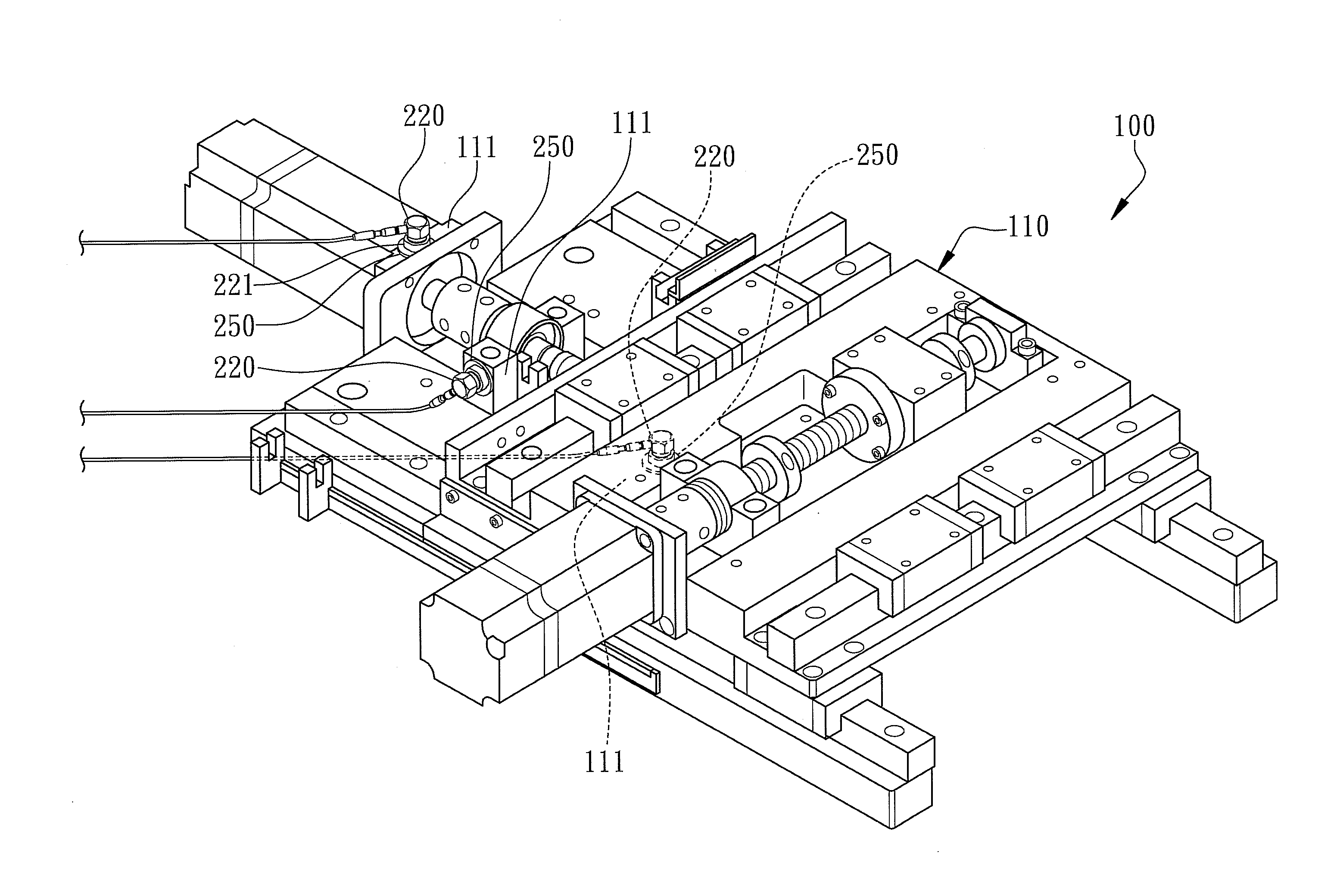
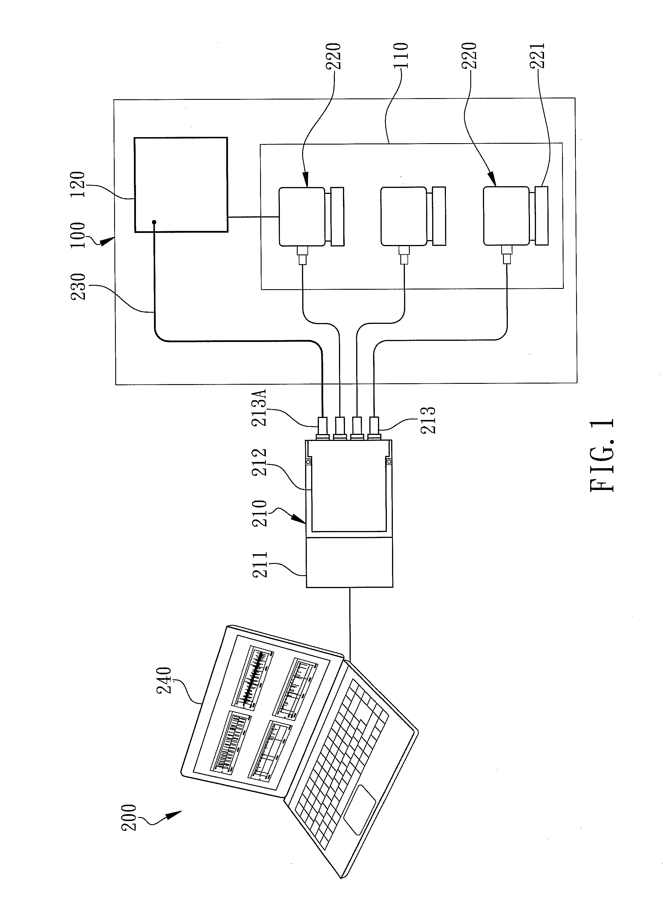
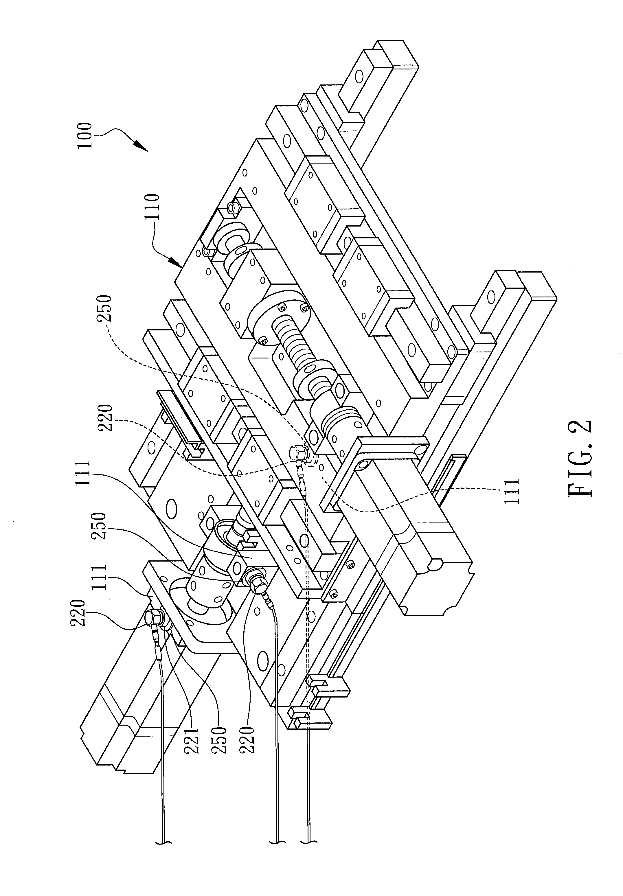
[0021]With reference to the attached drawings, the present invention is described by means of the embodiment(s) below where the attached drawings are simplified for illustration purposes only to illustrate the structures or methods of the present invention by describing the relationships between the components and assembly in the present invention. Therefore, the components shown in the figures are not expressed with the actual numbers, actual shapes, actual dimensions, nor with the actual ratio. Some of the dimensions or dimension ratios have been enlarged or simplified to provide a better illustration. The actual numbers, actual shapes, or actual dimension ratios can be selectively designed and disposed and the detail component layouts may be more complicated.

[0022]According to the first embodiment of the present invention, a controlling device 200 of semiconductor processing equipment 100 is illustrated in FIG. 1 for a major structural drawing. The controlling device 200 includes...


PUM


Abstract

Disclosed in this invention is a controlling device for abnormality prediction of semiconductor processing equipment. The controlling device includes a multiplexer connecting a plurality of vibration sensors to a spectrum analyzer. Therein, the vibration sensors are non-destructively installed to a variable-frequency rotating mechanism inside the semiconductor processing equipment. The multiplexer includes an adapter and at least a modularized multi-channel connecting assembly plugged into the adapter where the number of the connected vibration sensors is less than the number of the signal connecting terminals of the multiplexer so that at least one terminal is unconnected with the vibration sensors. Additionally, a control signal wire connects the unconnected terminal to a corresponding controller of the variable-frequency rotating element. The vibration spectrum analyzer is configured to record and collect both vibration signals and control signals where these signals are transformed into time-domain waveforms to track the lifetime of the equipment, to predict the failure of the equipment, and to reduce equipment down time, parts waiting time, and equipment repair time of the semiconductor processing equipment.

Description

FIELD OF THE INVENTION[0001]The present invention relates to controlling devices and controlling methods to handle semiconductor devices or parts, and more specifically to a controlling device and a controlling method for abnormality prediction of semiconductor processing equipment.BACKGROUND OF THE INVENTION[0002]There are various semiconductor processing equipments in the production line of semiconductor fabrication such as die bonders, wire bonders, molding equipment, etc. Since the existing prediction maintenance methodology is not well-developed and not really implemented in semiconductor processing equipment, therefore, regular maintenance is the only way to prevent sudden failure and to extend the lifetime of parts of semiconductor processing equipment where equipment engineers have to adjust semiconductor processing equipment while running or to shut down semiconductor processing equipment to maintain or disassemble and repair. Even with the best efforts, semiconductor proce...

Claims


Application Information

Patent Timeline
IPC IPC(8): G06F19/00G01N29/44
CPCH01L21/67288
Inventor LIN, CHENG-WEI
Owner POWERTECH TECHNOLOGY
Learn More